Sharp AN-CM250 Specifications Page 36
- Page / 97
- Table of contents
- TROUBLESHOOTING
- BOOKMARKS
- SHARP CORPORATION 1
- Introduction 2
- WARNING: 3
- PRODUCT DISPOSAL 3
- INFORMATION 3
- Declaration of Conformity 3
- Contents 4
- Easy to Use Functions 5
- Appendix 5
- IMPORTANT SAFEGUARDS 6
- SharpVision Manager 9
- Quick Guide 10
- Part Names 11
- Projector (Rear View) 12
- Remote Control (Front View) 13
- Remote Control (Top View) 13
- Using the Remote Control 14
- 3 Insert the lower tab of the 14
- Accessories 15
- Connections and Setup 16
- Before Connecting 17
- Connecting the Power 17
- Connecting to Video Equipment 18
- Connecting to 19
- Component Video 19
- Equipment Using a 19
- Component Cable 19
- (INPUT 1 or 2) 19
- 1 Connect a DVI to HDMI cable 22
- Connecting to a Computer 23
- Using the DVI to 15-pin 23
- D-sub Adaptor and the 23
- RGB Cable (INPUT 5) 23
- Connecting to a Com 24
- Cable (INPUT 5) 24
- “Plug and Play” function 25
- 1 Connect an RS-232C cable to 26
- Connecting the Remote 27
- Control to the Projector 27
- 2 Remove your hands from the 28
- 2 Zooming is adjusted by mov 29
- Using the Lens Shift 30
- Audience 31
- Projection using a mirror 33
- Ceiling-mount setup 33
- Basic Operation 34
- Image Projection 35
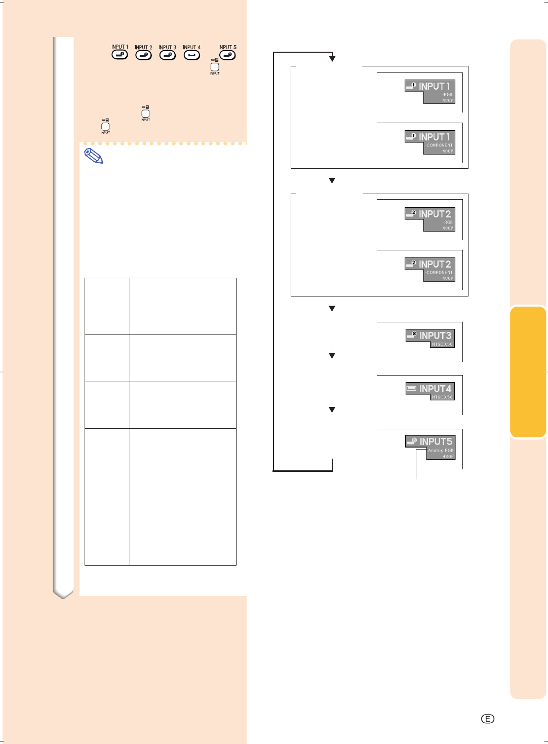
- 3 Press , , , or 36
- 1 Press 37
- 4 Press 37
- 1 Press on the remote control 38
- UNDO button 40
- Menu Bar Items 41
- Using the Menu Screen 43
- 2 Press 44
- 3 Press 44
- 4 Press 44
- 5 Press 44
- 5 Press 46
- 6 Press 46
- 7 Press 46
- Adjusting the Picture 47
- Adjusting Image Prefer 48
- Selecting the Gamma 48
- Position 48
- Selecting the C.M.S 49
- Special Settings 49
- Emphasizing the 51
- Contrast 51
- Reducing Image Noise 51
- Emphasizing Outlines 52
- Resetting All Adjust 52
- Adjusting the Gamma 53
- Selecting the Target 55
- Resetting User-Defined 57
- Color Settings 57
- Overview of All Color 57
- Settings 57
- Adjusting Computer Images 58
- Selecting Adjustment Settings 59
- Special Mode Settings 59
- Checking the Input Signal 60
- Auto Sync Adjustment 60
- Auto Sync Display 61
- Function 61
- Switching the Picture 63
- Display Using Different 63
- Input Signals 63
- COMPUTER 65
- Switching HIGH 66
- BRIGHTNESS MODE/ 66
- HIGH CONTRAST MODE 66
- Digital Shift Function 67
- Subtitle Setting 67
- LED Off Function 68
- Setting On-screen Display 69
- Selecting the Signal Type 70
- Setting the Video System 71
- Setting a Background Image 71
- Selecting the Economy Mode 72
- Selecting the Transmis 73
- Automatic Power Off 73
- Setting the Projection 74
- Overview of All Menu 75
- Neutral detergent 77
- Cleaning 77
- Cleaner 78
- Maintenance Indicators 79
- Regarding the Lamp 81
- 1 Press 82
- 2 Disconnect the power cord 82
- 3 Remove the lamp unit cover 82
- 4 Remove the lamp unit 83
- 5 Insert the new lamp unit 83
- 6 Attach the lamp unit cover 83
- 1 Connect the power cord 83
- 2 Reset the lamp timer 83
- Connecting Pin Assignments 84
- PC control 85
- Communication conditions 85
- Basic format 85
- Commands 85
- Computer Compatibility Chart 89
- Troubleshooting 90
- Specifications 92
- Dimensions 93
- Glossary 94
- VALID IN USA ONLY 96
- Consumer Electronics Products 97
Related products and manuals for Data projectors Sharp AN-CM250
 (73 pages)
 (70 pages)
(10 pages)
(18 pages)
(77 pages)
(16 pages)
(70 pages)
(10 pages)
(18 pages)
(77 pages)
(16 pages)
© 2020, manymanuals.com. All rights reserved. | 3.111 s |
 Manymanuals.com
 Manymanuals.de
 Manymanuals.fr
 Manymanuals.it
 Manymanuals.pl
 Manymanuals.cz
 Manymanuals.es
 Manymanuals-pt.com
Comments to this Manuals