Sharp PMP300 Service Manual
Browse online or download Service Manual for Microwaves Sharp PMP300. R-1500 R-1501 R-1505 R [en] [it] User Manual
- Page / 44
- Table of contents
- TROUBLESHOOTING
- BOOKMARKS
- SERVICE MANUAL 1
- BEFORE SERVICING 2
- WARNING TO SERVICE PERSONNEL 3
- SERVICE MANUAL 5
- PRODUCT SPECIFICATION 6
- GENERAL INFORMATION 6
- OVEN DIAGRAM 7
- CONTROL PANEL 8
- OPERATION 9
- Hood Fan 10
- TROUBLESHOOTING GUIDE 13
- CK = Check / RE = Replace 14
- TEST PROCEDURES 15
- QKITPB035 22
- TOUCH CONTROL PANEL ASSEMBLY 23
- During cooking 24
- 16.7 msec 24
- SEG24-SEG22 25
- SEG21-SEG0 25
- SERVICING 26
- WARNING AGAINST HIGH VOLTAGE: 27
- WARNING FOR WIRING 27
- OUTER CASE REMOVAL 28
- POWER TRANSFORMER REMOVAL 28
- HOOD FAN MOTOR REMOVAL 28
- MAGNETRON REMOVAL 29
- COOLING FAN MOTOR REMOVAL 30
- POSITIVE LOCK 31
- Key unit 32
- DOOR REPLACEMENT 33
- DOOR DISASSEMBLY 34
- Figure S-1. Pictorial Diagram 35
- Figure S-3. LSI Unit Circuit 37
- LOT NO 38
- PARTS LIST 39
- SCREWS,NUTS AND WASHERS 41
- OVEN AND CABINET PARTS 42
- CONTROL PANEL PARTS 43
- MISCELLANEOUS 43
- DOOR PARTS 43
Summary of Contents
R-1500R-1501R-1505R-1506In the interest of user-safety the oven should be restored to its originalcondition and only parts identical to those specifie
8R-1500R-1501R-1505R-1506VENTILATION METHODS HOT AIR EXHAUST1. VERTICAL VENTINGFor this venting method, hot air rising from theconventional range belo
9R-1500R-1501R-1505R-1506SCHEMATICNOTE: CONDITION OF OVEN1. DOOR CLOSED.2. COOKING TIME PROGRAMMED.3. VARIABLE COOKING CONTROL "HIGH".4. &qu
10R-1500R-1501R-1505R-1506DESCRIPTION AND FUNCTION OF COMPONENTS3. If the door is opened, and the secondary interlock relay(RY2) and primary interlock
11R-1500R-1501R-1505R-1506TROUBLESHOOTING GUIDENever touch any part in the circuit with your hand or an uninsulated tool while the power supply is con
12R-1500R-1501R-1505R-1506CK = Check / RE = ReplacePOSSIBLE CASE AND DEFECTIVE PARTSPROBLEMTEST PROCEDURECONDITIONOFFCONDITIONIDLECONDITIONMICROWAVECO
13R-1500R-1501R-1505R-1506B POWER TRANSFORMER TESTTEST PROCEDURESPROCEDURELETTERCOMPONENT TEST1. Disconnect the power supply cord, and then remove out
14R-1500R-1501R-1505R-1506TEST PROCEDURESPROCEDURELETTERCOMPONENT TEST1. Disconnect the power supply cord, and then remove outer case.2. Open the door
15R-1500R-1501R-1505R-1506TEST PROCEDURESPROCEDURELETTERCOMPONENT TEST1. Disconnect the power supply cord, and then remove outer case.2. Open the door
16R-1500R-1501R-1505R-1506I BLOWN MONITOR FUSE TESTTEST PROCEDURESPROCEDURELETTERCOMPONENT TEST1. Disconnect the power supply cord, and then remove ou
17R-1500R-1501R-1505R-1506TEST PROCEDURESPROCEDURELETTERCOMPONENT TESTResistance between;BLU (1) AND YLW (4) = 0Ω (Shorted)BLK (2) AND YLW (4) = 33ΩBL
R-1500R-1501R-1505R-1506PRECAUTIONS TO BE OBSERVED BEFORE ANDDURING SERVICING TO AVOID POSSIBLE EXPO-SURE TO EXCESSIVE MICROWAVE ENERGY(a) Do not oper
18R-1500R-1501R-1505R-1506TEST PROCEDURESPROCEDURELETTERCOMPONENT TEST8) Run the oven and check all functions.2. Control Unit.The following symptoms
19R-1500R-1501R-1505R-1506TEST PROCEDURESPROCEDURELETTERCOMPONENT TEST1. Disconnect the power supply cord, and then remove outer case. Refer to proced
20R-1500R-1501R-1505R-1506TEST PROCEDURESPROCEDURELETTERCOMPONENT TEST1. Foil pattern check and repairs.1) Disconnect the power supply cord.2) Open th
21R-1500R-1501R-1505R-1506DESCRIPTION OF LSILSIThe I/O signal of the LSI is detailed in the following table.Pin No. Signal I/O Description1-2 VL2-VL1
22R-1500R-1501R-1505R-150615 P53 OUT Terminal not used.16 P52 OUTOven lamp, fan motor and turntable motor driving signalTo turn on and off shut off re
23R-1500R-1501R-1505R-150637 P23 OUT Key strobe signal.Signal applied to touch-key section. A pulse signal is input to P43-P46 terminal while one ofG4
24R-1500R-1501R-1505R-15061. Precautions for Handling Electronic ComponentsThis unit uses CMOS LSI in the integral part of thecircuits. When handling
25R-1500R-1501R-1505R-1506Microwave ovens contain circuitry capable of producing very high voltage and current, contact with following parts mayresult
26R-1500R-1501R-1505R-1506REMOVAL OF OVEN FROM WALL (Two persons recommended to remove the oven)1. Disconnect the power supply cord, and uncoil the po
27R-1500R-1501R-1505R-15064. Disconnect the 6-pin connector of the hood fan motorfrom the main wire harness located at the right edge ofthe oven cavit
1R-1500R-1501R-1505R-1506WARNING TO SERVICE PERSONNELMicrowave ovens contain circuitry capable of pro-ducing very high voltage and current, contact wi
28R-1500R-1501R-1505R-15061. Disconnect the power supply cord, remove the ovenfrom wall and remove outer case (Refer to procedure of"Removal of O
29R-1500R-1501R-1505R-15061. Disconnect the power supply cord.2. Open the door and block it open.3. To discharge the high voltage capacitor, wait for
30R-1500R-1501R-1505R-150613.Remove the two (2) screws holding the LCD holder tothe key fixing plate.14.Remove two (2) screws holding the power unit t
31R-1500R-1501R-1505R-1506After adjustment, check the following.1. In and out play of door remains less than 0.5mm when inthe latched position. First
32R-1500R-1501R-1505R-15061. Disconnect the power supply cord.2. Open the door and block it open.3. To discharge the high voltage capacitor, wait for
33R-1500R-1501R-1505R-1506645123645123ABCDEFGHABCDEFGHFigure S-1. Pictorial DiagramHIGH VOLTAGERECTIFIERHIGH VOLTAGECAPACITORHIGH VOLTAGEWIRE AHIGH VO
34R-1500R-1501R-1505R-1506645123645123ABCDEFGHABCDEFGHFigure S-2. Power Unit CircuitN.OC 1C 7C 3C 5C12C 4C 9C 2C 8C 6C13C14E 2E 1C11C10N.OCOMCOMB 7B 9
35R-1500R-1501R-1505R-1506Figure S-3. LSI Unit Circuit645123645123ABCDEFGHABCDEFGHC 5C 1C 7C 2C 9C 8C 3C 6C 4C12C11C14G11G12 G 9G 8KEY UNITPOPCORN RIC
36R-1500R-1501R-1505R-1506645123645123ABCDEFGHABCDEFGHFigure S-4. Printed Wiring Board0FCSM27A 94V 0MBMR350RBFBDIPLOT NO.QKITPB035MRE0RY1VRS1R30T1S85
37R-1500R-1501R-1505R-1506PARTS LISTNote: The parts marked “∆” may cause undue microwave exposure.The parts marked “*” are used in voltage more than 2
2R-1500R-1501R-1505R-1506MICROWAVE MEASUREMENT PROCEDUREA. Requirements:1) Microwave leakage limit (Power density limit): The power density of microwa
38R-1500R-1501R-1505R-1506REF. NO. PART NO. § DESCRIPTION Q'TY CODE∆∆∆∆∆∆∆∆∆∆∆∆∆SP1 RALM-A014DRE0 J Buzzer (PKM22EPT) 1 AGT1 RTRNPB017MRE0 M Tran
39R-1500R-1501R-1505R-1506HOW TO ORDER REPLACEMENT PARTSTo have your order filled promptly and correctly, please furnish the following information.1.
40R-1500R-1501R-1505R-1506645123645123ABCDEFGHABCDEFGHOVEN AND CABINET PARTS6-1-54-102-64-177-61-106-94-184-172-26-126-87-11-147-57-57-57-57-36-107-34
41R-1500R-1501R-1505R-1506645123645123ABCDEFGHABCDEFGH6-66-76-116-16-1-16-1-26-1-36-1-76-1-86-1-56-1-66-1-45-2-33-2-33-2-13-2-25-2-35-2-25-2-15-25-35-
42R-1500R-1501R-1505R-1506COPYRIGHT © 2001 BY SHARP CORPORATIONALL RIGHTS RESERVED.No part of this publication may be reproduced, storedin retrieval s
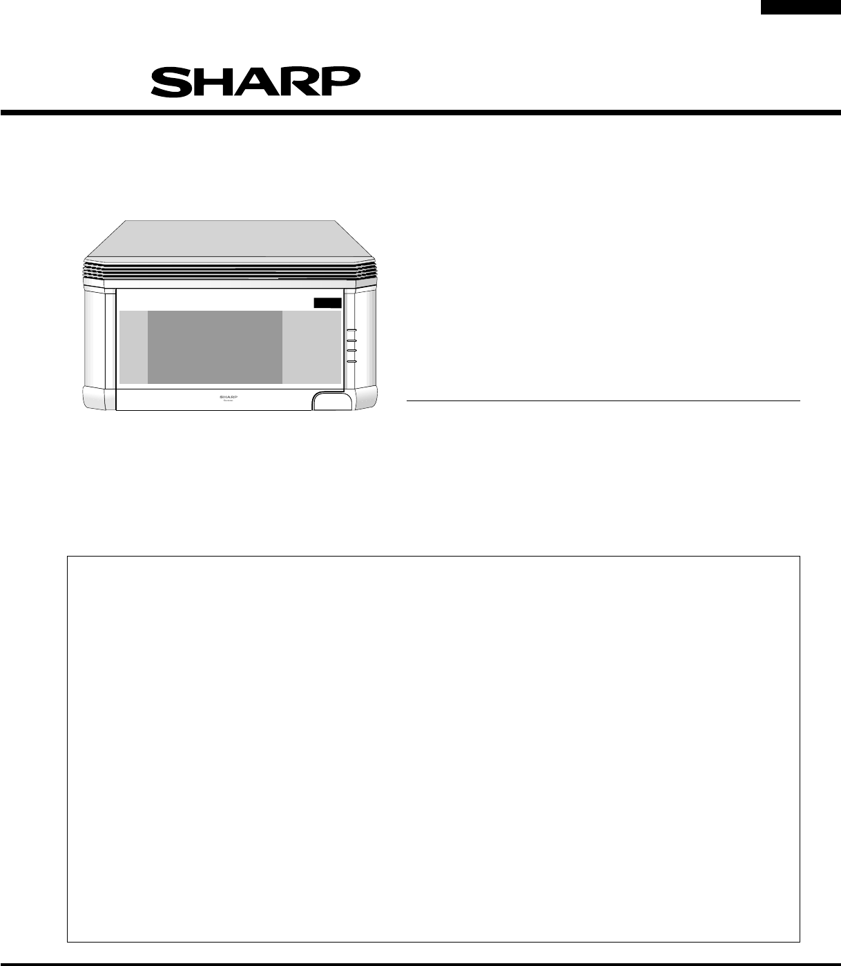
3R-1500R-1501R-1505R-1506SHARP ELECTRONICS CORPORATIONSHARP PLAZA, MAHWAH,NEW JERSEY 07430-2135SERVICE MANUALOVER THE RANGEMICROWAVE OVENR-1500/ R-150
4R-1500R-1501R-1505R-1506ITEM DESCRIPTIONPower Requirements 120 Volts / 14 Amperes60 HertzSingle phase, 3 wire groundedPower Output 1000 watts (IEC TE
5R-1500R-1501R-1505R-1506Electrical RequirementsThe oven is equipped with a 3-prong grounding plug. DO NOT UNDER ANY CIRCUMSTANCES CUT OR REMOVE THEGR
6R-1500R-1501R-1505R-15061000WATTSNO.LBS.OZ.CUPSCOOK DEFROSTKEEPWARMBAKEDPOTATOESFROZENVEGETABLESGROUNDMEATGROUNDMEATPOWERLEVELTIMERCLOCKPOULTRYBONELE
7R-1500R-1501R-1505R-1506OPERATIONDESCRIPTION OF OPERATING SEQUENCEThe following is a description of component functions duringoven operation.OFF COND
Related products and manuals for Microwaves Sharp PMP300
 (47 pages)
(44 pages)
(72 pages)
(48 pages)
(40 pages)
(16 pages)
(54 pages)
(392 pages)
(16 pages)
(52 pages)
(36 pages)
(40 pages)
(26 pages)
(16 pages)
(44 pages)
(1 pages)
(44 pages)
(47 pages)
(44 pages)
(72 pages)
(48 pages)
(40 pages)
(16 pages)
(54 pages)
(392 pages)
(16 pages)
(52 pages)
(36 pages)
(40 pages)
(26 pages)
(16 pages)
(44 pages)
(1 pages)
(44 pages)
© 2020, manymanuals.com. All rights reserved. | 0.078 s |
 Manymanuals.com
 Manymanuals.de
 Manymanuals.fr
 Manymanuals.it
 Manymanuals.pl
 Manymanuals.cz
 Manymanuals.es
 Manymanuals-pt.com
Comments to this Manuals