Sharp XL-3000 Service Manual
Browse online or download Service Manual for AV receivers Sharp XL-3000. Sharp XL-3000 Service manual User Manual
- Page / 64
- Table of contents
- TROUBLESHOOTING
- BOOKMARKS
- SERVICE MANUAL 1
- SPECIFICATIONS 2
- NAMES OF PARTS 3
- Remote control 4
- Setting the Clock 5
- Remote Control 5
- Accesorios 6
- Conexiones del sistema 6
- Audición de la radio 6
- DISASSEMBLY 7
- ADJUSTMENT 10
- XL-3000/3000C 11
- TEST MODE 11
- NOTES ON SCHEMATIC DIAGRAM 20
- WAVEFORMS OF CD CIRCUIT 21
- FM MPX/AM IF 30
- LA1832S 30
- FM IF DET/ 30
- 8 9 10 11 12 31
- PLL(TUNER) 31
- TERMINAL PWB-A4 34
- TUNER PWB-A2 36
- POWER PWB-B 36
- TROUBLESHOOTING 38
- 1.5~2.5sec 41
- FUNCTION TABLE OF IC 44
- 123456789 53
- XL-3000 55
- XL-3000C 55
- ALL RIGHTS RESERVED 64
Summary of Contents
– 1 –XL-3000/3000CSERVICE MANUALSHARP CORPORATIONNo. S4122XL3000U/This document has been published to be usedfor after sales service only.The content
XL-3000/3000C– 10 –ADJUSTMENTTUNER SECTIONAMGNDFM75OHMSANTENNATERMINALSO301T302IC301T306T304IC303T351L303L302VR351TP301FM MuteLevelAM BandCoverage fLF
– 11 –XL-3000/3000CTEST MODEThe test mode applied to this microcomputer has three modes, namely the ordinary test mode for adjustment or measurement,t
XL-3000/3000C– 12 –Press the following buttons in this state to obtain the operations specified below."POWER" ... Test mode and
– 13 –XL-3000/3000CThe time display always indicates "0:00".Press the following buttons in this state to obtain the operations specified bel
XL-3000/3000C– 14 –Press the following buttons in this state to obtain the operations specified below."POWER" ...Test mode and
– 15 –XL-3000/3000CPress the following buttons in this state to obtain the operations specified below."POWER" ...Test mode and
XL-3000/3000C– 16 –3. Tuner Test Mode (TEST 2)1. Outline of tuner (radio) test mode The tuner test mode is intended to store the adjustment and mea
– 17 –XL-3000/3000C4. Electronic volume Test Mode (TEST 3)When this test mode is obtained, the following display lights for one second.In this mode, v
XL-3000/3000C– 18 –6. LCD Test Mode (TEST 5)When the LCD test mode is obtained, all the LCD segments are lighted. Then pressing the "PLAY" b
– 19 –XL-3000/3000Ca. POWER ON for function AUXCD lid position is checked.CLOSE position: Operation proceeds to the next process.Position other than C
XL-3000/3000C– 2 –FOR A COMPLETE DESCRIPTION OF THE OPERATION OF THIS UNIT, PLEASE REFERTO THE OPERATION MANUAL.IMPORTANT SERVICE NOTES (FOR U.S.A. ON
XL-3000/3000C– 20 –NSW801 PICKUP IN ON—OFFSW709 POWER ON—OFFSW710 CD LID OPEN/CLOSE ON—OFFSW711 FF/PRESET UP ON—OFFSW712 CD PLAY/PAUSE/TUNING UP ON—OF
– 21 –XL-3000/3000CWAVEFORMS OF CD CIRCUITNO DISC FOCUS SEARCH STOP PLAYFOO1 TMAX 1IC802 48pin FO+ 2SBOK2IC804 26pinIC802 12pinFO- 3 DMO 3IC804 2
XL-3000/3000C– 22 –Q802Q801Q901 Q902Q908 Q907Q861765432189101112 13 14 15CNP702CLID_SW CLID_UP CLID_PROCLID_DW BUCKBUS2BUS0BUS1BUS3CCE CD_RESPU_IN LIG
– 23 –XL-3000/3000CAC 120V,60Hz AC POWER SUPPLY CORDVOLTAGEREGULATOR3 1 3 2 1 USWD_5R6VP_CONTD_GND3 2 1 AC INPUTSOCKETAC120V,60Hz POWERTRANSFORMER(SUB
XL-3000/3000C– 24 –AMGNDFM75ohmsSO301 VSM AM RF OUT OUT ININCUT AM LOWFM/AM FM AFCAM OSCAM OSCFM DETSTEREOSDGND AM IF REG AM MIXOUT ININFM IF
– 25 –XL-3000/3000CVSM AM RF OUT OUT OUT INCUT AM LOWFM/AM MPX VCO MPX INMO/ST L-CHR-CH(AM/FM) PHASE PHASE IF OUTVCC FM DETSTEREOSDGND AM IF IN
XL-3000/3000C– 26 –ABCDEFGH123456• NOTES ON SCHEMATIC DIAGRAM can be found on page 20.1.6A/125V3.15A/125V3.15A/125V13V 20V 12.3V 12.2V 11.7V 20V 20V 2
– 27 –XL-3000/3000C78 9 10 11 124.8V4.8V0V0V4.8V4.8V4.8V4.8V0V0V0V5.1V5.1V5.1V5.1V5.1V5.1V10.2V5V4.8V4.8V4.8V4.8V4.8V4.8V4.8V4.8V0V0V0.14V0.14V4.8V9.6
XL-3000/3000C– 28 –ABCDEFGH1234560V0V5V2.2V2.6V2.1V1.8V2.1V2.1V2.1V2.1V0V0V0V0V0V0V0V0V0V0V0V0V5V5V5V5V5V5V1.4V1.7V2.5V2.5V1.2V2.4V0.6V4.3V2.1V2.1V0V5
– 29 –XL-3000/3000C78 9 10 11 125V6.3V3.4V4.1V2V2.1V2.1V2.1V2.1V2.1V2.1V2.1V2.1V2.1V2.1V2.1V2.1V2.1V2.1V2.1V2.2V2.2V1.7V0V0V5V2.5V4.3V3.4V+B+B+B+B+B1.
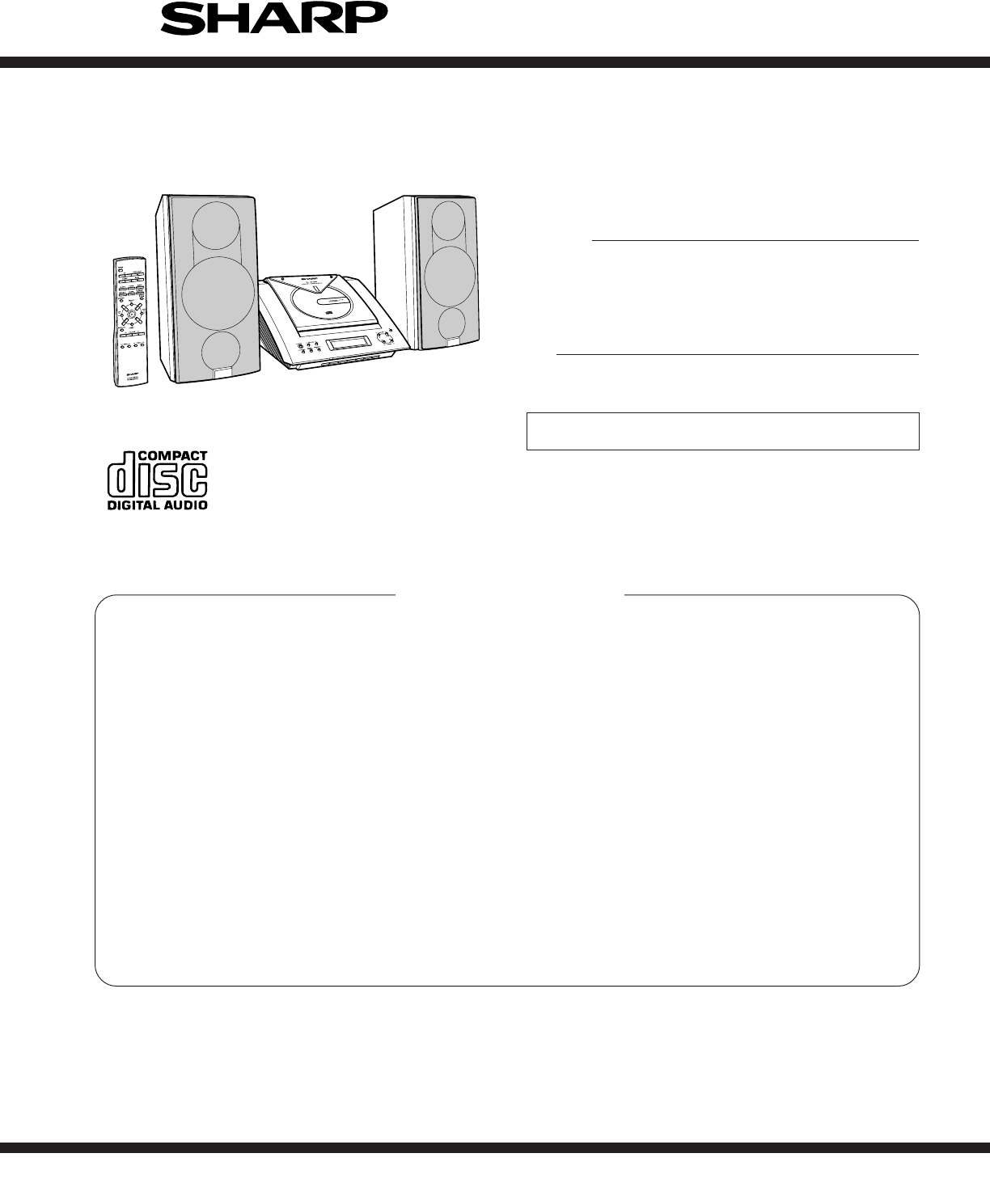
– 3 –XL-3000/3000CNAMES OF PARTS Front panel1. CD Compartment2. Volume Up and Down Butto ns 3. Power Button 4. Function Selector Button5. Memor
XL-3000/3000C– 30 –ABCDEFGH1234565V2.5V5V21V2.1V5.2V5.2V5.2V0V0V0V2.1V0V0V5.2V1.5V1.5V0.8V3.8V4.4V2.6+B+B+BFM IF DET/FM MPX/AM IFFM FRONT ENDPLLFM IFF
– 31 –XL-3000/3000C78 9 10 11 120.6V2.3V2.3V (0V)1.3V1.3V4V(2.2V)0V (0.9V)5V2.1V (2.7V)2.1V (2.7V)2.1V(1.2V)3.8V(1.9V)3.8V(4.3V)2.9V0V0V5V5V5V5V2.1V2.
XL-3000/3000C– 32 –ABCDEFGH123456+B+B+B+B+B+B+B1.1V0V0V0.1V0.1V4.1V4.5V0.4V0.4V+B+B+B+B+B2.47V2.47V2.47V2.47V0V0V0V0V0V0V0V4.9V0V0V0V0V0V2.5V2.5V2.5V2
– 33 –XL-3000/3000C78 9 10 11 12+B+B+B+B+B+B0V0V0V0V4.8V4.8V4.76V4.72V0V0V4.9V4.9V4.8V4.8V4.8V5V5V5V5V5V2.5V2.5V2.5V2.5V2.5V2.5V2.5V2.5V2.5V2.5V2.5V2.
XL-3000/3000C– 34 –ABCDEFGH123456R122R120R121R119R110R102R124R609R608R604R607R603R613R623R621R80FR80CR80ER80AR9R624R101R103C109C104Q101Q104Q102C120R11
– 35 –XL-3000/3000C78 9 10 11 12R80CR80ER80AC843C849R80BR824C860R862IC804 C858R863R861C830C825C887R820C826C827C823C824C819R814C821R812C818R811R810C817
XL-3000/3000C– 36 –ABCDEFGH123456C397R379R381C302C349C329C331R323C335C319C305IC301C313C314C303C308C309C304C317C310R358C343R314R302T304R313C350R312R316
– 37 –XL-3000/3000C78 9 10 11 122R708R706R710R711R720B R749R721R702C703R722R724R728C701R723C702R727R732R729R707R720A R7A6R7A2R7A7C712R7A8C704R7A5R7A0R
XL-3000/3000C– 38 –TROUBLESHOOTINGCleaner LiquidCleaning DiscPARTS CODE: UDSKA0004AFZZHOW TO USE1. Using the brush in the cleaner cap, apply 1 or 2 dr
– 39 –XL-3000/3000CMake sure that the disc is normal, and set the CD TEST MODE (STEP 1).Is the measured voltage as specified in circuit diagram?Check
XL-3000/3000C– 4 – Speaker system1. Tweeter2. Woofer3. Bass Reflex Duct4. Speaker Terminals1243Speaker grilles are removable:Make sure nothing comes i
XL-3000/3000C– 40 –Check the PWB pattern between emiter of Q607 and emiter ofQ861.• Laser failure.Is 0V applied to the pin 57 (SEL) of IC802 ?YesNoDoe
– 41 –XL-3000/3000C• Focus servo sawtooth wave failure.Is +6.2V applied to the pins 21 and 22 (VCC) of IC804 ? Is sawtooh wave output to the pin 48 (F
XL-3000/3000C– 42 –• HF error.YesYesIs output (tracking error signal) obtained at the pins 46 (TEI)and 47 (TEZI) of IC802 the CD TEST MODE "STEP
– 43 –XL-3000/3000C• Sled motor operation failure.YesYesIs following sled feed signal output the pin 53 (FMO) of IC802when FF /REW key is pressed
XL-3000/3000C– 44 –FUNCTION TABLE OF ICIC401 VHiLC75342M-1: Function/Volume Equalizer (LC75342M)1 DI Serial data and clock input pin for control.2 CE
– 45 –XL-3000/3000CIC401 VHiLC75342M-1: Function/Volume Equalizer (LC75342M)67891011 12 13 1415 16 17 18 19 202122232425265272830291234LVrefRVrefCCBI
XL-3000/3000C– 46 –1-4 COM3-COM0 Output LCD common output terminal.5-7 VLC3-VLC1 — LCD power supply terminal.8 VDD Input Microcomputer power supply +5
– 47 –XL-3000/3000CFunctionTerminal NameInput/Output54 SEG46 P63/A3 Output Electric JOG dial UP.55* SEG45 P64/A4 Output Electric JOG dial DOWN.56 SEG4
XL-3000/3000C– 48 –IC801 VHiTA2109F/-1:Servo Pre Amp. (TA2109F)1 VCC — Power voltage terminal2 FNI Input Main beam amp input terminal3 FPI Input Main
– 49 –XL-3000/3000CIC802 VHiTC9462F/-1: Servo/Signal Control (TC9462F) (1/3)1* TEST0 Input Test mode terminal. To be opened usually.2* /HSO Output Pla
– 5 –XL-3000/3000COPERATION MANUALSetting the ClockThis may be operated only with the remote control.In this example, the clock is set for the 12-hour
XL-3000/3000C– 50 –39 AVDD Input Analog system power terminal.40 RFCT Input RFRP signal center level input terminal.41 RFZI Input RFRP zero cross inpu
– 51 –XL-3000/3000C83 DVDD Input D/A converting section power terminal.84 DVR Input Reference voltage terminal.85 LO Output L channel data forward rot
XL-3000/3000C– 52 –IC804 VHiMM1469XH-1: Focus/Tracking/Spin/Sled Driver (MM1469XH)In this unit, the terminal with asterisk mark (*) is (open) termina
– 53 –XL-3000/3000CLCD701: RV-LX0012SJZZ LCD DisplayFigure 53 LCD SEGMENTPinNo123456789101112131415161718192021com1com1z1h1g1a1RECh2g2a2SLEEPh3g3a3RAN
XL-3000/3000C– 54 ––MEMO–
XL-3000/3000CPARTS GUIDENOTE:Parts marked with “ ” are important for maintaining the safety of the set.Be sure to replace parts with specified ones fo
PRICERANKDESCRIPTIONNO.PARTS CODENO. PARTS CODEPRICERANKDESCRIPTIONXL-3000/3000C– 1 –INTEGRATED CIRCUITSIC201 VHIKIA4558P-1 J AC Surround Control,KIA4
NO.PRICERANKDESCRIPTIONPARTS CODENO. PARTS CODEPRICERANKDESCRIPTIONXL-3000/3000CC311 VCCCCY1HH100J J AA 10 pF(CH),50VC312 VCCSCY1HL330J J 12 pF,50VC31
PRICERANKDESCRIPTIONNO.PARTS CODENO. PARTS CODEPRICERANKDESCRIPTIONXL-3000/3000CR7A6 VRS-CY1JB102J J AA 1 kohm,1/16WR7A7 VRS-CY1JB102J J AA 1 kohm,1/1
NO.PRICERANKDESCRIPTIONPARTS CODENO. PARTS CODEPRICERANKDESCRIPTIONXL-3000/3000CR806 VRS-CY1JB153J J AA 15 kohms,1/16WR807 VRS-CY1JB103J J AA 10 kohm,
XL-3000/3000C– 6 –AccessoriesAccesorios1122Speaker wire × 2Cable del altavoz × 2Remote control × 1Controlador remoto × 1AC power cord × 1Cable de alim
PRICERANKDESCRIPTIONNO.PARTS CODEXL-3000/3000CPRICERANKDESCRIPTIONNO.PARTS CODE231 PGUMS0002SJZZ J Cushion,CD Lid232 PRDAR0044SJFW J Radiator,Main233
XL-3000/3000CABCDEFGH123456Figure 6 CD MECHANISM EXPLODED VIEW– 6 –302301NM802 702x2307x2306x2NSW801NM801308-2308305308-1308-3704x2303304703701703PWB
XL-3000/3000CFigure 7 CABINET EXPLODED VIEWABCDEFGH123456– 7 –SiliconGreaseSiliconGreasePWB-A2PWB-A8PWB-A8PWB-BPWB-A7PWB-A3PWB-A1PWB-A5PWB-A6601x2206
XL-3000/3000C– 8 –Figure 8 SPEAKER EXPLODED VIEWABCDEFGH123456SP3 (L-CH)SP4 (R-CH)SP1 (L-CH)SP2 (R-CH)SP3 (L-CH)SP4 (R-CH)TweeterTweeterCapacitor909C
XL-3000/3000CPACKING OF THE SET (FOR U.S.A. ONLY)Setting position of switches and knobsCD Lid CLOSEPacking Add.,Top/BottomSPAKA0068SJZZ: Not Replaceme
– 7 –XL-3000/3000C1Rear Panel/Terminal PWB1. Screw ... (A1) x7 7-12. Socket ... (A2) x33. Screw ... (A3) x
XL-3000/3000C– 8 –(E2) x7ø3 x8mm(E2) x1ø3 x14mm(C1) x1ø3 x6mm(D1) x1(E1) x1Power PWBMain PWB(D2) x1Hook(C1) x1ø3 x8mmHolder PWBTuner PWBMain PWB(C2) x
– 9 –XL-3000/3000CHow to remove the CD lid (See Fig. 9-1.)Perform steps 1,2 and 8 of the disassembly method to removethe gear box.(See page 7,8)1. Rem
© 2020, manymanuals.com. All rights reserved. | 1.434 s |
 Manymanuals.com
 Manymanuals.de
 Manymanuals.fr
 Manymanuals.it
 Manymanuals.pl
 Manymanuals.cz
 Manymanuals.es
 Manymanuals-pt.com
Comments to this Manuals