Sharp SJ-380N Service Manual
Browse online or download Service Manual for Unknown Sharp SJ-380N. Sharp SJ-380N Service manual User Manual
- Page / 33
- Table of contents
- BOOKMARKS
- SERVICE MANUAL 1
- Refrigerator-freezer 1
- CHAPTER 1. SPECIFICATION 2
- Service Manual 3
- SJ-A31S/A34S 3
- DESIGNATION OFVARIOUS PARTS 4
- [2] CONSTRUCTIONS 5
- CHAPTER 3. DIMENTIONS 6
- (Unit:mm) 7
- [2] INNER DIMENTIONS 8
- 4. SJ-A31S 10
- 5. SJ-A34S 10
- LIST OF ELECTRICAL PARTS 11
- SJD26LVSL 12
- WIRING DIAGRAM 12
- F-LOUVER ASS’Y 13
- 3. Soldering 14
- 1. Employing lead-free solder 14
- CHAPTER 6. FAILURE DIAGNOSIS 15
- Varistor 16
- [5] CONVERSION TABLE 17
- CHAPTER 7. FUNCTIONS 19
- Freezer Temp. Control Knob 20
- 1. Fan motor ass'y 21
- 2. EV-cover ass'y 22
- 3. F - louver ass'y 23
- Figure A-4 24
- Figure A-2 24
- Figure A-3 24
- Detail of D 24
- WIRE COLOR IS GRAY/ORANGE 24
- Fuse ass’y 25
- L-band c 25
- Glass cloth tape 25
- Figure A-5 25
- [3] R CONTROL COV. ASS'Y 27
- Figure A-12 28
- Figure A-13 28
- Control label 28
- R-Control knob 28
- [4] HOW TO REPLACE THE LAMP 29
- [5] DEFROST HEATER 30
- Heater support 31
- Def. heater ass'y 31
- Heater cover 31
- CHAPTER 9. COOLING UNIT 32
- [2] LOCATION 33
Summary of Contents
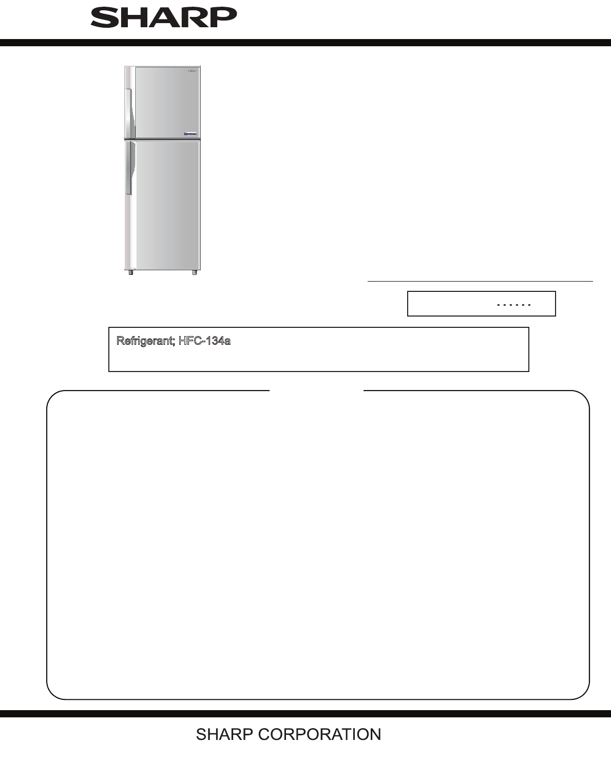
SERVICE MANUALSJ-A20S/B21S/A24S/B25S/A28A/B27S/A31S/A34S-SLNo.S9902SJ22FTVTTThis document has been published to be used forafter sales service
3 – 54. SJ-A31S5. SJ-A34S43038335543138445472472472411217152217259330147170210530217451113809210766662312542041542171208091180682373010767430430674166
4 – 1SJ26NSL CHAPTER 4. LIST OF ELECTRICAL PARTSITEMS TYPE NAME RATING SPECIFICATIONSR ThermistorDefrost Thermistor――DC 5VDC 5VR0 = 6.4 kΩ, B(0) = 38
5 – 1SJD26LVSLCHAPTER 5. WIRING DIAGRAM[1] WIRING DIAGRAMBe sure to replace the electrical parts with specified ones for maintaining the safety and pe
5 – 2[2] ELECTRIC ACCESSORIES LAYOUTF-LOUVER ASS’YFAN MOTORFMLEAD EV COVERFUSEDEF-THERMISTORDEF-HEATERR-CBOX-KPWBLAMPR-THERMISTORDOOR SWITCHTERMINAL C
5 - 3 1. Employing lead-free solderThe PWB of this model employs lead-free solder. This is indicated by the "LF" symbol printed on the PWB a
6 – 1SJ431NSLService Manual CHAPTER 6. FAILURE DIAGNOSIS[1] OUTLINE OF CONTROL1. ON/OFF Control of CompressorWhen the plug of refrigerator is connecte
6 – 2[3] RE-SETTING OF MICROCOMPUTER AT POWER FAILURE• At the power failure for over 0.1 second, the control of the microcomputer will be reset.When t
6 – 3[5] CONVERSION TABLEConversion Table between R-thermistor and Def-thermistor Temperature and Resistance ValueTemperature(°C)Resistance Value(kΩ)T
6 – 4[6] CIRCUIT DIAGRAM OF MAIN PWB !"#$% &'$( &#$) &'$* &#$+ &'$, &#-( &#-)
7 – 1SJD26LVSLCHAPTER 7. FUNCTIONS[1] ADJUSTABLE TEMPERATURE CONTROL1. Temperature control1) FREEZER COMPARTMENTThe FREEZER TEMP. CONTROL regulates th
1 – 1SJD34NSLGService Manual CHAPTER 1. SPECIFICATIONRATINGPLUG TYPEPlug cord 2 pinPlug type -Destination mark TCOLORItems -SLOutside c
7 – 23. Temp. control systemAmbient temperatureRefrigerator compartment temperature (at the center position)Freezer compartment temperature (at MID po
8 – 1SJD26LVSLCHAPTER 8. ASSEMBLING PROCEDURES OF MAIN PARTS AND CAUTIONSCAUTION: DISCONNECT THE UNIT FROM THE POWER SUPPLY BEFORE ANY REPAIRING.[1] F
8 – 22. EV-cover ass'y1. Bind Fuse ass'y with L-band c. Then wind glass cloth tape (W25 x L50mm ) to lead wire of Fuse ass'y (Figure A-
8 – 33. F - louver ass'y1. Set F-louver to front side of EV-cover with double face tape (W15xL45mm.).2. Insert F-control knob to F-louver. Then s
8 – 4[2] F-LOUVER ASS'Y (SJ-A31S/A34S)1. Fan motor ass'y1. Stick U-sealer handle to Fan motor holder a (Fig. A-2).2. Insert the terminal of
8 – 52. EV-cover ass'y1. Bind Fuse ass'y with L-band c. Then wind glass cloth tape (W25 x L50mm ) to lead wire of Fuse ass'y (Figure A-
8 – 63. F - louver ass'y1. Set F-louver to front side of EV-cover with double face tape (W15xL45mm.).2. Insert F-control knob to F-louver. Then s
8 – 7[3] R CONTROL COV. ASS'Y1. Insert Lead R-Thermistor to Lead R-C Box.2. Inset Lead R-C box to PWB L ass'y.3. Assemble the PWB L ass’y w
8 – 85. Assemble Lamp with R-C Box cover then fix with 2 tapping screw.6. Stick Knob sealer on R-C Box cover and then insert Knob joint to R-C Box cov
8 – 9[4] HOW TO REPLACE THE LAMP1. Remove the Light cover.2. Remove the 2 screw, and pull the Lamp out.3. Insert the new Lamp to the connector, and fi
1 – 2SJD34NSLGService Manual RATINGPLUG TYPEPlug cord 2 pinPlug type -Destination mark TCOLORItems -SLOutside color Silver Inside colo
8 – 10[5] DEFROST HEATER1. Taking-out Evaporator1. Take-out Fan louver ass’y. 2. Take-out E.V cover ass’y.3. As shown in Figure A-15, pull the upper p
8 – 114. Replace Def. heater ass’y with new one.5. Bend end of heater support 90. 6. Assemble Defrost heater to Heater Support.7. Assemble Heater cove
9 – 1SJ26NSLService Manual CHAPTER 9. COOLING UNIT[1] COOLING UNITNOTE: The iron pipe is partly used of this refrigerator. Please note the following p
9 – 2[2] LOCATION1. Location 12. Location 2* Copper back condenser is used in some models.Before repairing,check the Back condenser is copper or iron.
2 – 1SJ26NSLService Manual CHAPTER 2. DESIGNATION OFVARIOUS PARTS[1] EXTERNAL DESCRIPTIONThe names in parenthesis "[ ]" are the denominat
2 – 2[2] CONSTRUCTIONSFan motorDef-thermistorF-temp. control knobR-temp. control knobEvaporatorDefrost heaterDeodorizing unitR-thermistorPWB L ass&apo
3 – 1SJD26LVSLCHAPTER 3. DIMENTIONS[1] OUTER DIMENTIONS AND CLEARANCE1. SJ-A20S/B21S2. SJ-A24S/B25S(Unit:mm)9344610628.510855451145365970545443.5757.5
3 – 23. SJ-A28S/B27S(Unit:mm)9344610628.510855451145365970545515.5923.514916060 604. SJ-A31S600600541.5986.534410651161122140563115809649.5 !"#$%
3 – 35. SJ-A34S600541.51106.534463111616001221405106517009649.5[2] INNER DIMENTIONS1. SJ-A20S/B21S3803902533214514614930067107671965543391383313841741
3 – 42. SJ-A24S/B25S(Unit:mm)1965543380390453913833138169417417363208180371366366673010767137208253271214187434204154103250143107661208091211292683404
Related products and manuals for Unknown Sharp SJ-380N


 (30 pages)
(235 pages)
(40 pages)
(12 pages)
(12 pages)
(230 pages)
(12 pages)
(24 pages)
(13 pages)
(30 pages)
(15 pages)
(36 pages)
(30 pages)
(235 pages)
(40 pages)
(12 pages)
(12 pages)
(230 pages)
(12 pages)
(24 pages)
(13 pages)
(30 pages)
(15 pages)
(36 pages)

 (89 pages)

 (210 pages)
(69 pages)
(210 pages)
(69 pages)
 (11 pages)
(41 pages)
(14 pages)
(118 pages)
(11 pages)
(41 pages)
(14 pages)
(118 pages)
© 2020, manymanuals.com. All rights reserved. | 0.710 s |
 Manymanuals.com
 Manymanuals.de
 Manymanuals.fr
 Manymanuals.it
 Manymanuals.pl
 Manymanuals.cz
 Manymanuals.es
 Manymanuals-pt.com
Comments to this Manuals