Sharp AL-1555 Series Specifications
Browse online or download Specifications for Copiers Sharp AL-1555 Series. Sharp AL-1555 Series Specifications User Manual
- Page / 89
- Table of contents
- TROUBLESHOOTING
- BOOKMARKS

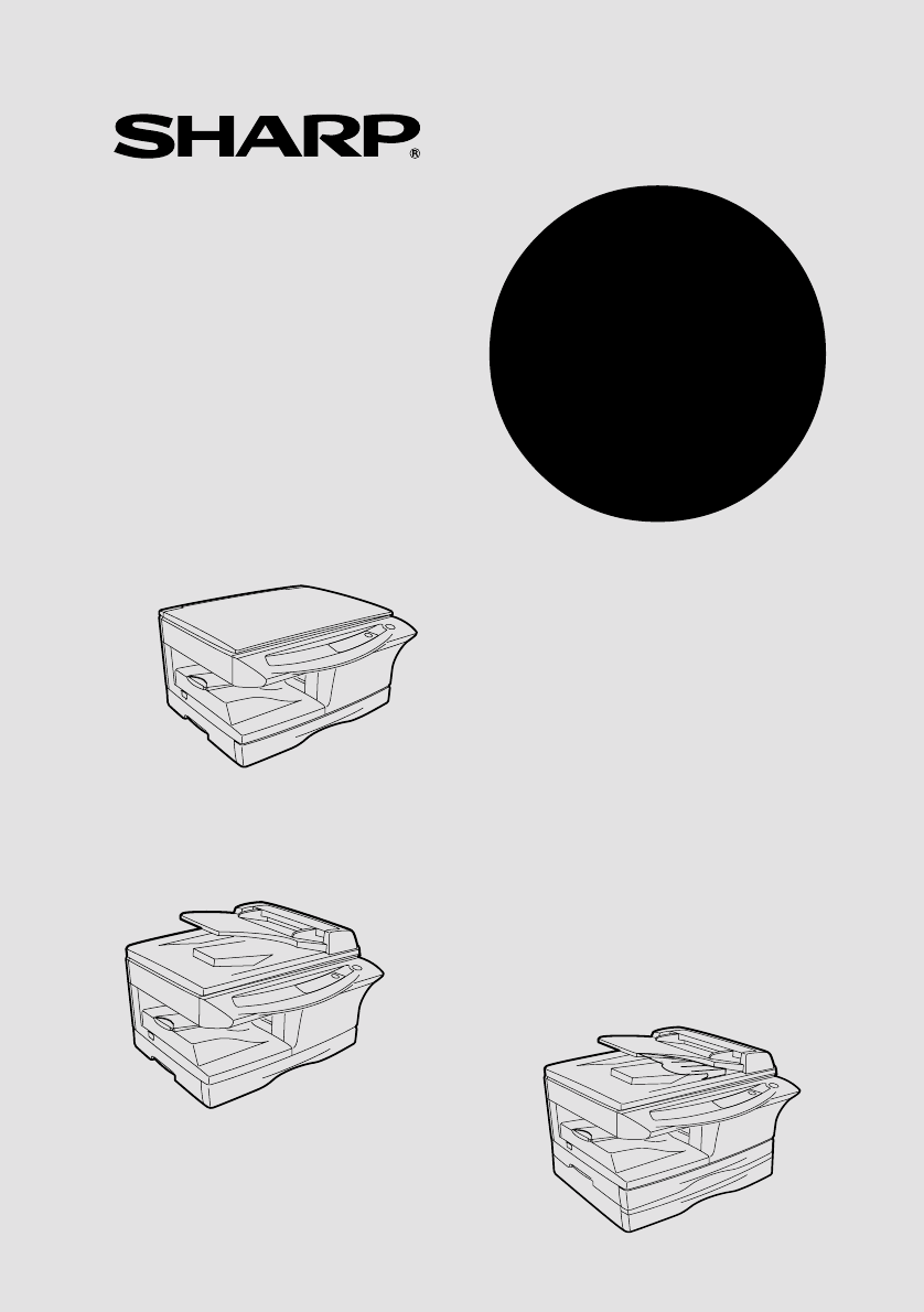
- OPERATION MANUAL 1
- LASER PRODUCT 2
- LASER KLASSE 1 2
- CAUTIONS 3
- Cautions on handling 4
- Cautions on laser 4
- Trademark acknowledgements 4
- CONTENTS 5
- INTRODUCTION 6
- PART NAMES 7
- OPERATION PANEL 8
- SETTING UP THE UNIT 9
- ACCESSORIES 10
- Lock Unlock 11
- Grasp here and turn in 11
- INSTALLING THE TD CARTRIDGE 12
- CONNECTING THE POWER CORD 14
- Power off methods 15
- LOADING PAPER 16
- LOADING THE PAPER TRAY 17
- Print face 19
- The single bypass (AL-1552) 20
- INSTALLING THE SOFTWARE 21
- BEFORE INSTALLATION 22
- Flow of installation 23
- (Parallel interface) 31
- Start indicator 34
- ONLINE indicator 34
- Power save indicator 34
- SCANNER indicator 34
- USING THE PRINTER MODE 35
- USING THE SCANNER MODE 37
- This is the Control Panel 40
- Cameras" 40
- Click here 42
- HOW TO USE THE ONLINE MANUAL 45
- USING OTHER INSTALLED DRIVERS 46
- MAKING COPIES 48
- ORIGINAL PLACEMENT 49
- Using the SPF/RSPF 50
- SET THE COPY QUANTITY 51
- Automatic exposure adjustment 52
- REDUCTION/ENLARGEMENT/ZOOM 53
- SPECIAL FUNCTIONS 54
- AL-1552_AL-1553 55
- TONER SAVE MODE 56
- USER PROGRAMS 57
- MAINTENANCE 59
- DRUM CARTRIDGE REPLACEMENT 60
- CLEANING THE UNIT 61
- Transfer charger 62
- TROUBLESHOOTING THE UNIT 63
- STATUS INDICATORS 64
- MISFEED REMOVAL 65
- B: Misfeed in the fusing area 66
- Feeding roller 67
- Feeding roller cover 68
- (AL-1555) 69
- APPENDIX 70
- ABOUT SUPPLIES AND OPTIONS 72
- MOVING AND STORING THE UNIT 73
- INDEX BY PURPOSE 76
- SOFTWARE LICENSE 77
- 6. Limited Warranty on Media 78
- 8. Limitation of Liability 78
- 10. Complete Agreement 78
- Page: 1/4 79
- Page: 2/4 80
- Page: 3/4 81
- Page: 4/4 82
- PRINTED IN FRANCE 89
- TINSE1409TSZ1 89
Summary of Contents
AL-1552AL-1553AL-1555DIGITAL MULTIFUNCTIONAL SYSTEMOPERATION MANUAL
8CHECKING PACKED COMPONENTS AND ACCESSORIESOpen the carton and check if the following components and accessories are included.If anything is not inclu
922Remove all pieces of tape shown in the illustration below. Then open the original cover/SPF/RSPF and remove protective materials. After that, take
10INSTALLING THE TD CARTRIDGE1Open the multi-bypass tray (AL-1553, AL-1555, p.17), and then open the side cover.2Push gently on both sides of the fron
1125Close the front cover and then the side cover by pressing the round projections near the side cover open button.When closing the covers, be sure t
12CONNECTING THE POWER CORD1Ensure that the power switch of the unit is in the OFF position. Insert the attached power cord into the power cord socket
132About the scan headThe scan head lamp remains on constantly when the unit is in the ready condition (when the start ( ) indicator is illuminated).T
14Follow the steps below to load paper into the tray.PAPERFor best results, use only paper recommended by SHARP.* Do not use non-standard envelopes, a
153LOADING THE PAPER TRAY1Raise the handle of the paper tray and pull the paper tray out until it stops.2Remove the pressure plate lock. Rotate the pr
165Fan the paper and insert it into the tray. Make sure the edges go under the corner hooks.6Gently push the paper tray back into the unit.Do not load
173BYPASS FEED (including special paper)The multi-bypass tray (AL-1553, AL-1555) or the single bypass (AL-1552) can be used to feed standard paper, tr
CLASS 1 LASER PRODUCTLASER KLASSE 1LUKOAN 1 LASERLAITEKLASS 1 LASERAPPARATVAROITUS!LAITTEEN KÄYTTÄMINENMUULLA KUIN TÄSSÄKÄYTTÖOHJEESSA MAINITULLATAVAL
18The single bypass (AL-1552) 1Select copy settings before you begin the copy job.For information on the copy settings, see "MAKING COPIES"
194This chapter explains how to install the software that allows the AL-1552, AL-1553 and AL-1555 to be used as a printer and scanner, and the proced
20HARDWARE AND SOFTWARE REQUIREMENTSCheck the following hardware and software requirements in order to install the software.*1Compatible with Windows
214Flow of installationRefer to the following table and then begin installation.OperatingsystemInterface Reference pages for how to installWindows XPU
22INSTALLING THE SOFTWAREThe following term is used in this section.MFP Means the unit as a printer and scanner.Installing onto Windows XP (USB/parall
2345Review the software packages to be installed on the screen, and then click the "Start" button.The software packages to be installed will
247Begin installation of the Button Manager (This step will start if it was selected in step 4).1After confirming the message in the "Welcome&quo
25410Make sure that the power of the MFP is turned on, and then connect the USB interface cable or parallel interface cable. (p.45)Windows will detect
26Installing onto Windows 98/Me/2000 (USB interface)Before starting the installation, make sure the USB interface cable is not connected to the MFP.1I
2746Copying files for MFP driver installation.1After confirming the message in the "Welcome" window, click the "Next" button.2A di
1CAUTIONSCaution label on the unitThe label ( ) in the fusing area of the unit indicates the following:: Caution, risk of danger: Caution, hot surface
288Begin installation of the Sharpdesk (This step will start if it was selected in step 4).1After confirming the message in the "Welcome to Sharp
294Installing onto Windows 95/98/Me/NT4.0/2000 (Parallel interface)Before starting the installation, make sure the USB or parallel interface cable is
307Copying files for MFP driver installation and parallel interface setup (This step will start if it was selected in step 4).1After confirming the me
3148Begin installation of the Sharpdesk (This step will start if it was selected in step 4).1After confirming the message in the "Welcome to Shar
32INDICATORS ON THE OPERATION PANELThe ONLINE indicator and the start ( ) indicator indicate the state of the printer or scanner.Start indicatorOn: In
334USING THE PRINTER MODEOpening the printer driver from the start menuOpen the printer driver setup screen by either of the methods shown below.1Clic
343Make sure that "SHARP AL-xxxx" (where xxxx is the model name of your unit) is selected as the current printer. If you intend to change a
354USING THE SCANNER MODEThe scanner driver for this unit includes an STI (Still image) driver and WIA (Windows Image Acquisition) driver. You can ins
36Windows 98/Me/2000To scan directly into an application using the Button Manager on Windows 98, Windows Me and Windows 2000. Set the Event Manager pr
374Scan Parameter Settings Dialog BoxAfter you have completed the Button Manager settings in Windows, configure the scan settings in Button Manager. T
2Cautions on handlingBe careful in handling the unit as follows to maintain the performance of this unit. Do not drop the unit, subject it to shock or
38The settings for the Windows Event Manager for the SHARP AL-xxxx (where xxxx is the model name of your unit) device allow the user to take advantage
394Using the SCANNER key to begin scanning1Press the SCANNER ( ) key.The unit enters scan mode.2Place the original you wish to scan on the original ta
404Press the start ( ) key.Scanning will start and the scanned data will be transferred to the application.Opening the scanner driver and scanning fro
4143Select "SHARP Personal MFP series", and click the "Select" button.4Select "Acquire Image" from the "File"
42Scanning with the "Scanner and Camera Wizard" in Windows XPWindows XP includes as a standard feature an image scanning function. The proce
434HOW TO USE THE ONLINE MANUALThe online manual provides detailed instructions for operating the unit as the printer or scanner and a list of methods
44USING OTHER INSTALLED DRIVERSIf you use another GDI printer or a Windows Printing System printer, interference between printers may occur and printi
454CONNECTING THE INTERFACE CABLEThis unit includes both USB and parallel interface connectors.Interface cables for connecting the unit to your comput
46This chapter explains basic and other copying functions.The unit is equipped with a one-page memory buffer. This memory allows the unit to scan an o
475About interrupt copyingIf you press the start ( ) key to begin a copy job while a print job using the papertray or multi-bypass tray is in progress
31243568791 INTRODUCTIONUSING THE MANUALS... 4PART NAMES...5 OPERATION PANEL... 62 SETTI
48Setting a large original (AL-1552)The original cover can be removed to allow copying of bulky objects.1Simply lift the original cover straight up.2T
495Stream feeding modeThe stream feeding mode allows easy operation of continuous copying from the SPF/RSPF. If the stream feeding mode has been enabl
50Automatic exposure adjustmentThe automatic exposure level can be adjusted to suit your copying needs. This level isset for copying from the original
515REDUCTION/ENLARGEMENT/ZOOMThree preset reduction ratios and two enlargement ratios can be selected. The zoom function enables copy ratio selection
52This chapter describes the special functions of this unit. Use these functions as needed.TWO SIDED COPYINGWhen copying from the SPF/RSPF, two-side o
536A: When copying in a one-sided to two-sided mode:Use the original to copy key to select the desired one-sided to two-sided copying mode (Turn on Lo
541234DESCRIPTION OF SPECIAL FUNCTIONSToner save mode (page 54)Reduces toner consumption by approximately 10%.Power save modes (page 55)The unit has t
5562Press and hold down the exposure mode selector key for approximately 5 seconds. The MANUAL ( ) indicator will go out and the PHOTO ( ) indicator w
56* Factory default settings are indicated with an asterisk (*).5Press the start ( ) key. The right-hand number in the display will be steadily lit an
577This chapter describes how to replace the TD cartridge and drum cartridge, and how to clear the unit.TD CARTRIDGE REPLACEMENTThe TD cartridge repla
4This chapter provides basic information for using the unit.USING THE MANUALSIn addition to this printed manual an online manual is also provided. To
584Close the front cover and then the side cover by pressing the round projections near the side cover open button. The indicator ( ) will go out and
5974Gently install the TD cartridge. To install the TD cartridge, see "INSTALLING THE TD CARTRIDGE" (p.10).5Close the front cover and then t
60Transfer chargerIf copies start becoming streaky or blotchy, the transfer charger may be dirty. Clean the charger using the following procedure.1Tur
618This chapter describes misfeed removal and troubleshooting.For problems with the printer function or the scanner function, see the online manual or
62STATUS INDICATORSWhen the following indicators light up or blink on the operation panel or the following alphanumeric codes appear in the display, s
638MISFEED REMOVALWhen the misfeed ( ) indicator blinks or blinks in the display, the unit will stop because of a misfeed. If a misfeed occurs when
64A: Misfeed in the paper feed area1Gently remove the misfed paper from the paper feed area as shown in the illustration. When the misfeed ( ) indicat
6582Gently remove the misfed paper from under the fusing unit as shown in the illustration. If the paper cannot be removed, proceed to "C: Misfee
66D: Misfeed in the lower paper feed area (AL-1555)1Open the lower side cover (under the manual tray) and remove the misfed paper. If blinks and the
678(B) Open the SPF/RSPF and rotate the roller rotating knob to remove the misfed original from the exit area. If the misfed original cannot be easily
51PART NAMESInterfaceTD cartridge Drum cartridgeSPF (AL-1553)RSPF (AL-1555)Original cover(AL-1552)Originalexit area23415768910111314157Single bypass(A
68SPECIFICATIONSModel AL-1552 AL-1553 AL-1555Type Digital multifunctional system, desk-top typeCopy system Dry, electrostatic transferOriginals Sheets
699*1Feed paper lengthwise only.*2Leading and trailing edges.*3Along the other edges in totals.*4The trailing edge of the second (Two-sided copy mode)
70ABOUT SUPPLIES AND OPTIONSWhen ordering supplies, please use the correct part numbers as listed below.Supply list* Based on copying onto letter-type
719MOVING AND STORING THE UNITMoving instructionsWhen moving the unit, follow the procedure below.1Turn the power switch off and remove the power cord
72INDEXAAcrobat Reader ... 43Alarm indicator- Drum replacement required indicator...6, 58, 62
73MMaking copies ...46MFP driver- Print Status Window...19- Printer driver...
74UUSB interface cable...45, 70Using other installed drivers ... 44Using the manuals... 4Usin
75SOFTWARE LICENSEPLEASE READ THIS LICENSE CAREFULLY BEFORE USING THE SOFTWARE. BYUSING THE SOFTWARE, YOU ARE AGREEING TO BE BOUND BY THE TERMS OFTHIS
766. Limited Warranty on Media.SHARP warrants the disks on which the Software is recorded to be free from defects in materials and workmanship under n
MATERIAL SAFETY DATA SHEET Page: 1/4 Date Revised: Jul. 31. 2002 Date Issued : Jun. 1. 1998 MSDS No. F-00831 1. PRODUCT AND COMPANY IDEN
6OPERATION PANELAL-1555A5A4A4B5A4A51418670Original to copy key and indicatorsTwo-sided copies from one-sided originals.Turn on Long Edge or Turn on Sh
MATERIAL SAFETY DATA SHEET Page: 2/4 Date Revised: Jul. 31. 2002 Date Issued : Jun. 1. 1998 MSDS No. F-00831 3.HAZARDS IDENTIFICATION Mos
MATERIAL SAFETY DATA SHEET Page: 3/4 Date Revised: Jul. 31. 2002 Date Issued : Jun. 1. 1998 MSDS No. F-00831 Personal Protective Equipmen
MATERIAL SAFETY DATA SHEET Page: 4/4 Date Revised: Jul. 31. 2002 Date Issued : Jun. 1. 1998 MSDS No. F-00831 Chronic Effect : In
MATERIAL SAFETY DATA SHEET Page: 1/4 Date Revised: Jul. 31. 2002 Date Issued : Jun. 1. 1998 MSDS No. F-30831 1.PRODUCT AND COMPANY IDENTIFICAT
MATERIAL SAFETY DATA SHEET Page: 2/4 Date Revised: Jul. 31. 2002 Date Issued : Jun. 1. 1998 MSDS No. F-30831 4.FIRST-AID MEASURES Route
MATERIAL SAFETY DATA SHEET Page: 3/4 Date Revised: Jul. 31. 2002 Date Issued : Jun. 1. 1998 MSDS No. F-30831 9.PHYSICAL AND CHEMICAL PROPERTIES
MATERIAL SAFETY DATA SHEET Page: 4/4 Date Revised: Jul. 31. 2002 Date Issued : Jun. 1. 1998 MSDS No. F-30831 13.DISPOSAL CONSIDERATIONS W
Attention: Your product is marked with this symbol. It means that used electrical and electronic products should not be mixed with general household
The CE mark logo label is affixed on an equipment in case that the directives described in the above sentence areapplicable to the product. (This sent
PRINTED IN FRANCETINSE1409TSZ1
72Follow the installation procedure below to use the unit properly.SETUP PROCEDUREWhen using the unit for the first time, setup the unit following the
Related products and manuals for Copiers Sharp AL-1555 Series
 (187 pages)
(12 pages)
(54 pages)
(28 pages)
(98 pages)
(110 pages)
(12 pages)
(80 pages)
(188 pages)
(311 pages)
(148 pages)
(40 pages)
(4 pages)
(18 pages)
(100 pages)
(76 pages)
(220 pages)
(148 pages)
(187 pages)
(12 pages)
(54 pages)
(28 pages)
(98 pages)
(110 pages)
(12 pages)
(80 pages)
(188 pages)
(311 pages)
(148 pages)
(40 pages)
(4 pages)
(18 pages)
(100 pages)
(76 pages)
(220 pages)
(148 pages)
© 2020, manymanuals.com. All rights reserved. | 0.031 s |
 Manymanuals.com
 Manymanuals.de
 Manymanuals.fr
 Manymanuals.it
 Manymanuals.pl
 Manymanuals.cz
 Manymanuals.es
 Manymanuals-pt.com
Comments to this Manuals