Sharp JW-21MN User Manual
Browse online or download User Manual for Unknown Sharp JW-21MN. Sharp JW-21MN User's Manual
- Page / 114
- Table of contents
- BOOKMARKS
- Sharp Programmable Controller 1
- New Satellite JW20H/30H 1
- ME-NET module 1
- User's Manual 1
- Model name 1
- 30Hn mark 2
- (Compatible 2
- Safety Precautions 3
- Table of contents 6
- Chapter 2: Safety Precautions 10
- Joint using a 11
- 2-3 Treatment 12
- 2-4 Static electricity 12
- 2-5 Maintenance 12
- (Front view) 14
- (Rear view) 14
- Chapter 5: Installation 15
- The system consists of the 16
- 6-1 Processing cable end 17
- When the adjustment 18
- KEDAADFS 19
- Chapter 7: Wiring Method 22
- R45 or larger 24
- Straight 25
- Self-adhesive tape 25
- 7-6 Check after wiring 26
- 9-1 Communication method 33
- Top address of slave station 34
- "n" link area 34
- Number of sending bytes 34
- [2] Communication delay time 36
- : Receive 37
- 9-3 Expansion of network 38
- [2] Hierarchical link 39
- 10-1 Computer link function 40
- 10-2 Basic commands 41
- 10-3 Optional commands 42
- [1] Read free memory size 43
- [2] Monitor TMR, CNT, and MD 43
- [3] Reading PC mode 44
- [4] Setting PC mode 44
- [5] Reading system memory 45
- [6] Writing system memory 45
- [7] Reading date 46
- [8] Setting date 46
- [9] Reading time 47
- [10] Setting time 47
- [11] Correct clock time 48
- 15 21 03 49
- ACK CMD SUB 030 031 032 49
- Read out data 49
- (H), none 51
- 2B 43 4C 41 46 FD 00 52
- 2B 00 43 4C 41 46 FB 00 01 52
- ACK CMD SUB Enable 52
- [20] Response on error 53
- 11-1 Operation procedure 54
- [1] Mode switch (MODE) 55
- (Factory setting: OFF) 56
- (Rear side) 56
- Coaxial cable 57
- [1] Setting contents 58
- [2] Communication area map 60
- 24 24 24 61
- General 64
- [4] Setting procedure 66
- (JW-14JG) 67
- 04001 DCM 000 68
- 04002 DCM 001 68
- I PARAM 68
- >04003 DCM 003 68
- Convert to 69
- Convert to hexa 69
- (Word display) 70
- (Byte display) 70
- Screen display of JW-14PG 72
- Contents 74
- Corresponding 75
- 11-7 to 11-9 75
- [3] Setting procedure 77
- DCM (decimal) 78
- 12-1 Indication lamps 82
- 12-2 Flag 83
- Communication monitor 86
- 12-3 Storage of error code 87
- 7654321 0 88
- 00100000 88
- Error history storage area 89
- Operation procedure 90
- Chapter 14: Support Tools 91
- <Load> 92
- Chapter 15: Specifications 93
- 15-3 Data link specifications 94
- Basic rack 95
- Chapter 16: Appendix 96
- (1) Check flow chart 97
- (2) Check cable/connector 98
- (8) are all 00(H) 105
- Bit address 107
- △:Seen as a JW-22CU/50CUH 108
- □:Seen as a JW-50CU 108
- (standard JW30 model) 108
- Select "COM. set." 109
- (JW-21MN) 111
- Alphabetical Index 112
Summary of Contents
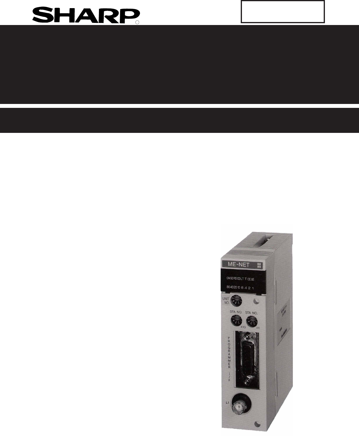
RSSharp Programmable Controller New Satellite JW20H/30HME-NET moduleJW-21MN Version 2.2Produced in April 2002User's ManualModel name
2-12"T" jacket(insulation cover)"L" jacket(insulation cover)Chapter 2: Safety Precautions2-1 InstallationDo not install or store
16-516- When the master station indicates error code 6F(H) and the COMM lamp lights.The cause may be a setting error of any of the slave stations whic
16-616When the COMM lamp of the master station is OFF (SD, RD, and CD are flickering).Check the following master station's parameters.Other cases
16-716(4) When the communication error occurs instantaneously.Cause may be:- Noise on the communication line.- Fault of a communication module.- Fault
16-81616-3 Table of parameter memory(1) Master stationThe set contents of the parameter addresses 004004 to 004377(8) and 004404 to 004777(8) shownbel
16-916* When 00(H) is set, the value becomes the same top address of the master station regardless ofthe setting value of 004404 to 004405(8).- Initia
16-1016(3 / 5)- Initial value of the address 005000 to 005177(8) are all 00(H).Address(8)005000005001005002005003Set contentsWhen 8 bytes, set to 0000
16-1116- Initial value of the address 005200 to 005377(8) are all 00(H).(4 / 5)Address(8)Set contents03(8) (same as 005202 to 005203)04(8) (same as 00
16-1216(5 / 5)- For initial values of above addresses, see page 11-5 and 6.(2) Slave station (01 to 77(8)) (1 / 1)- For initial values of above addres
16-131616-4 Special functions unique to the JW-21MNThe functions below are not covered by the ME-NET specifications. They can only be used with PCswhi
16-1416 Function< Standard network connection >The operations below using a peripheral device, that is connected to a "n" station, is
2-22Communication cables should be laid from the master station to the slave station one by one.Multiple wiring from one point or wiring without termi
16-1516- Network settingSelect whether the target station for remote programming or remote monitor is on thestandard network connection or on the exte
16-1616(2) Parameter setting by remote functionThis paragraph describes how to set the parameters of other stations' network module (JW-21MN/JW-2
I-1IAlphabetical Index[A]Allocation of relay number ... 2-3Append
I-2I[M]Maintenance and check ... 16-1Maintenance ...
I-3ISetting special I/O parameter ... 10-11Setting time ...
2-322-3 TreatmentFor ventilation, holes are provided in the cabinet to prevent a temperature rise. Do not block theventilation holes. Good ventilation
3-13Chapter 3: System Configuration- An example of system configuration using the JW-21MN as a master station- An example of system configuration usin
4-14Station No. switchSwitch1234567890UNIT NO.Module No. switchShield ground switchSTA NO.×11234567890×101234567890Mode switchABCDEF0123456789MODE0002
5-15 Turn "OFF" the power supply to the JW20/JW20H/JW30H. Set the mode switch, the termination resistance switch, and the shield ground swit
6-16Chapter 6: Processing of CablesMake sure to use the qualified products shown below for cables and connectors. Cable and connectorinstallation and
6-266-1 Processing cable end Applicable cableHigh frequency coaxial cable: ME-5C-2V Required toolsStripper for high frequency coaxial cable: CST-TM P
6-36Internal conductor(annealed copper single wire)10mmFrom the previous pagePut a coaxial cable while remaining approximately 10 mm intothe cable str
6-46Cut the internal conductor of the coaxial cable,which is already cut by the stripper, using a nipperetc. to the optimum dimension of 4 mm.Hold up
Thank you for purchasing the ME-NET module (JW-21MN) for the SHARP programmable controller.Read this manual thoroughly to completely familiarize yours
6-566-2 Connector crimping procedure Required tools: Hand-held crimping tool Connector: ME-GP-01 Processing procedureConnector partsShellSleeveContac
6-66Slightly widen the external conductor of thecoaxial cable, which is crimped to a contact onthe internal conductor, in order to smoothly enterthe s
7-17ME-JJ-01400mmBranch lineTrunk cable400mm max.Branch lineTrunk cableChapter 7: Wiring Method7-1 Cable trunk and branch lines On the illustration of
7-27(1) Fixing of the cableIn order not to put any force on the cable and theJW-21MN, fasten the cable to an line nearby input ofa control panel or a
7-37(6) Bending radius of the signal cable should be less than 45 mm (outside).- Specification of the cable manufacturer is that bending radius should
7-477-4 Waterproof and insulation processing of connectorsIn order to prevent water intrusion into the "T" branch connectors and the straigh
7-577-5 Wiring of cables at outside control panels Do not bundle the coaxial cable (the trunk and branch lines) together with power cables, andseparat
7-677-7 Wiring method for adding a communication station(1) Branching methodWhen branching a line for an additional station, be sure to branch from th
7-77(3) NotesWhen adding a communication station, follow the items below.Item ReasonAnother branch line from a branch line may not giveappropriate com
8-18Chapter 8: Memory Address on the ME-NETThe ME-NET employs a system for addressing individual memory banks in all of the connectedequipment by allo
Safety PrecautionsRead this manual and attached documents carefully before installation, operation, maintenance andchecking in order to use the machin
88-2(2) Memory address map (against JW30H)* ME-NET addresses for file 10 to 2C(H) are out of the range the ME-NET specification.These are special addr
8-388-2 Memory addresses for computer links- Data memory byte addresses in the computer link must be entered the same way a data link addressis entere
88-4* ME-NET addresses (SEG10 to 2C) of file 10 to 2C(H) are out of ranges of the ME-NETspecification. These are special addresses for the JW-21MN.- A
9-19- The link relay of the receiving station must be programmed as input signal by the PC program-ming. Also, it may be used as source (S) side of ap
9-29(2) Register linkMainly used for sending and receiving numerical data.[Example] In the case of sending 1 byte data from a master station and slave
9-399-2 Required transmission time and communication delay time[1] Required transmission timeThis is the time required for the master station to compl
9-49[2] Communication delay timeThe communication data on the ME-NET may have the delay shown below. Delay of input module Time required for PC to det
9-59[3] Data transmission between master PC and slave PCProviding synchronous transfer gives positive data communication.[An example of synchronized t
9-699-3 Expansion of networkThe JW-21MN can transmit data between 64 stations at maximum. If more than 64 stations arerequired for data link, you can
9-79MasterSlave01 02 03 04 05 06 07 10 11 12 13 14 15 16 17 20 21 Slave20 21 22 23 24 25 73 74 75 76 77 : Master stationSlave s
3) Use Danger- Don't touch the terminal while the power is being supplied or you may have an electric shock.- Assemble the emergency stop circuit
10-110Chapter: 10 Description for Computer Link OperationWhen connected to a host computer with a network module that is compatible with the ME-NETspe
10-21010-2 Basic commandsMeaning and available memory address ranges of each command are shown in the table below- Numeric values of each command are
10-31010-3 Optional commandsThe JW-21MN optional commands are any commands not specified in the ME-NET specifications.These are commands specific to t
10-410[1] Read free memory sizeRead free memory size.[Write mode assignment]: None[Communication format] Command ResponseEx. When reading the amount o
10-510[3] Reading PC modeRead PC's mode.[Write mode assignment]: None[Communication format] Command Response[Ex.] When the PC reads program mode
10-610[5] Reading system memoryRead the specified number of bytes of data from the specified address in system memory.[Write mode assignment]: None[Co
10-710[7] Reading dateRead the year, month, date, and day of week. However, when JW-21CU or JW-31CUH/H1 is used asPC, they do not have clock function
10-810[9] Reading timeRead out time (hour, minute, second) of clock. However, when JW-21CU or JW-31CUH/H1 is used asPC, these PC do not have clock fun
10-910[11] Correct clock timeCorrect the clock setting. However, when a JW-21CU or JW-31CUH/H1 is used as PC, they do nothave clock function and the r
10-1010[13] Read the optional parametersRead the parameter data for option module (other than JW-21MN) from the control module.[Write mode assignment]
ME-NET Module: JW-21MN- User's Manual -Chapter 1 Features and FunctionsChapter 2 Safety PrecautionsChapter 3 System ConfigurationChapter 4 Name a
10-1110[15] Read the special I/O parametersRead out parameter data of special I/O modules (other than JW-21MN) from the control module.[Write mode ass
10-1210[17] Set the secret function: JW30H onlyEnables the secret function, or deletes previously registered passwords.[Write mode assignment]- When c
10-1310[19] Check the secret function: JW30H onlyEnables/disables the secret function.[Write mode assignment]: None[Communication format] Command Resp
10-1410[20] Response on errorWhen a station that has received data encounters an error while processing data after receiving anoptional command from t
11-111Chapter 11: Setting of Switches and Parameter11-1 Operation procedure-Make sure to turn "OFF" the power of the PC prior to setting the
11-211[2] Module No. switch (UNIT NO.)Select error history storage registration area and data link (save memory function) area for a slavestation by s
11-31143210FEDCBA98765(Factory setting: OFF)ONOFFLT(Rear side)(4) Termination resistance switch (LT)When the JW-21MN is at the termination station of
11-41143210FEDCBA98765(Factory setting: ON)ONOFFLG(Rear side)(5) Shield ground switch (LG)For communication lines, use a coaxial cable.As coaxial cabl
11-51111-3 Setting contents of master station parameters[1] Setting contentsWhen the JW-21MN is used as a master station, set the following items for
11-611* Corresponding symbols on pages 11-7 to 11-9- to are equivalent to number of page 11-13.-Parameter addresses other than above mentioned are
Chapter 1: Features and Functions ... 1-1Chapter 2: Safety Precautions ...
11-711Slave station 01(8)(Data memory)Master station 00(8) (Data memory)Register link area(Within a total of 2048 bytes)Relay link area(Within a tota
11-811(2) In case that setting the data link (save memory function) when the master station and allslave stations are JW-21MN's.Memory addresses
11-911- Set the receiving area for save memory function within the range of the link area.0 £ a1 £ Total number of bytes of relay link area -h10 £ an
11-1011[Example for setting]The master station and slave station 01 and 02 are JW-21MN.It shows example for setting that slave station 01 is data link
11-1111コ1000Time limited contact000000000377000400000677I / O relayコ0000コ0377b0000Fileaddress(8)ByteaddressRelay link area setting range015000015777コ0
11-1211(2) When master station PC is JW30H- When master and slave stations areJW-21MN and set to data link (thestandard function) :- When slave stat
11-1311[4] Setting procedureSet parameters of the master station following the procedure below.
11-1411• key: Changeover unit of figures→HEX(hexadecimal) →OCT(octal) → DCM(decimal) →Bit patternTurn to program mode (stop PC operation).
11-1511LowerUpper00(H) · In case of standard function, set top address by file address(8). In case of save memory function, set number o
11-1611From the previous pageWrite 000200(8) in parameter ad-dresses 004004 to 004005(8).Write 000(8) (=00(H)) in parameter address 004006(8).Write 00
Chapter 10: Description for Computer Link Operation ... 10-1 to 1410-1 Computer link function ...
11-1711From the previous pageSet top address of register link area on slave station 01 to 77(8) (at standard function)/numberof offset bytes (at save
11-1811totoFrom the previous pageSet the number of sending bytes of the slave station (01 to 77) relay link [DCM (decimal), word] Set the number
11-1911Set connection status of slave station [bit pattern, byte]Set "connected slave station as 01 and 02, outputerror code" in paramente
11-2011Covert tohexadecimalfiguresSet top address of flag areaFrom the previous pageFile address: OCT (octal), wordFile number/flag: HEX (hexadecimal)
11-2111Writing to the EEPROM of the JW-21MN, start operation [HEX (hexadecimal), byte]From the previous pageWrite 81(H)Write "81(H)" into
11-221111-4 Setting slave station parameters (common for all slave stations) When the JW-21MN is used as a slave station, set the following items
11-2311• When PC is JW30H•When PC is JW20/JW20HFlag areas are allocated by 24 bytes from each top address. For setting the top address of flag area,us
11-2411[3] Setting procedure [ ] : See
11-2511Turn to program mode (stop PC operation). Setting of parameters is only available when the PC isin program mode.Select parameter setting mode.W
11-2611LowerUpper Set the number of sending bytes in decimal on the parameter address 007720 to 007721(8). Set the number of sending bytes in
12-3 Storage of error code ... 12-6Chapter
11-2711Covert tohexadecimalfiguresSet top address of flag areaFrom the previous pageFile address: OCT (octal), wordFile number/flag: HEX (hexadecimal)
11-2811Write 81(H)Writing to the EEPROM of the JW-21MN, start operation [HEX (hexadecimal), byte]From the previous pageWrite "81(H)" into
12-112Chapter 12: Errors and CountermeasuresThe operating condition of the JW-21MN can be monitored using its indication lamps, flags, and thesystem m
12-21212-2 FlagFlag area is 24 bytes from the "flag top address" set in the master station/slave station parameters.[1] Flag table [ In case
12-312[2] In the case of a master station(1) Communication monitor flagThis flag is used to monitor the communication condition with other stations. N
12-412[3] In the case of slave station 01 to 77(8)(1) Communication monitor flagThis flag is used to monitor the communication condition with other st
12-512[4] Monitor operation condition by each station PCBy creating a program having the flags shown below in each station's PC, the JW-21MN can
12-61212-3 Storage of error codeWhen an error occurs in the JW-21MN, it stores the occurred error’s code to system memory #160,#170 and error history
12-712(1) System memory #170 to 177 (option module error code)The error code stored in the system memory #170 is shifted to #170 to #177 one after the
12-812 (4) Error historyWhen the JW-21MN has errors, it stores them in an error history register. The storage area isspecified using the module No. sw
1-11Chapter 1: Features and FunctionsJW-21MN is a ME-NET module for JW20/JW20H/JW30H. Using this module, you can construct an ME-NET combining various
13-113StartTurn "OFF" the JW20/JW20H/JW30H's powerRemove the cables from the JW-21MNRemove the JW-21MN from the rack panelSet the switc
14-114After stopping operation, record the parameters of the JW-21MN onto the memory of the personal computer.(3) Start operation of the JW-21MNAfter
14-214<Load>(1) Load to the personal computerLoad the contents of the floppy diskette into the memory of the personal computer.Select "FD T
15-115Chapter 15: Specifications15-1 General specifications15-2 Communication specificationsApplicable PCInstalling slotStorage temperatureAmbient tem
15-21515-3 Data link specificationsBoth standard function and save memory function are available. Select by the mode switch on theJW-21MN.(1) Standard
15-31515-4 Computer link specifications[Outside dimensional drawings]ItemSpecifications64 stations max.Maximum 1024 bytes per commandAccording to the
16-116Chapter 16: Appendix16-1 Maintenance and checkCheck wiring, installation, and switch settings.ONCommunication cableJW-21MNNot parallel with or p
16-21616-2 Recovery method at communication errors(1) Check flow chartFirst communication?Does the error occur continuously?RecoverySee "When the
16-316(2) Check cable/connectorAs errors on the junction from the main cable to the drop cable or the contact failure on theconnecting point of each s
16-41603(8)Remove the connector on point A, and turn ON the termination resistance of the master station.07(8)06(8)05(8)Masterstation04(8)BD7OFFA CDis
Related products and manuals for Unknown Sharp JW-21MN
 (4 pages)
 (1 pages)
(81 pages)
(1 pages)
(1 pages)
(81 pages)
(1 pages)
 (2 pages)
(8 pages)
(1 pages)
(11 pages)
(16 pages)
(15 pages)
(3 pages)
(16 pages)
(4 pages)
(2 pages)
(8 pages)
(1 pages)
(11 pages)
(16 pages)
(15 pages)
(3 pages)
(16 pages)
(4 pages)

 (44 pages)
 (40 pages)
(16 pages)
(69 pages)
(1 pages)
(40 pages)
(16 pages)
(69 pages)
(1 pages)
© 2020, manymanuals.com. All rights reserved. | 0.371 s |
 Manymanuals.com
 Manymanuals.de
 Manymanuals.fr
 Manymanuals.it
 Manymanuals.pl
 Manymanuals.cz
 Manymanuals.es
 Manymanuals-pt.com
Comments to this Manuals