Sharp R-430EK Service Manual
Browse online or download Service Manual for Microwaves Sharp R-430EK. Sharp R-430EK Service manual [en] [pl] User Manual
- Page / 36
- Table of contents
- BOOKMARKS
- SERVICE MANUAL 1
- (RD21101U) 2
- (RD81001 U) 2
- Before Servicing 4
- After repairing 4
- SPECIFICATIONS 5
- Key Unit Layout 6
- OPERATION 7
- Troubleshooting Guide 8
- Sensor Cooking Condition 8
- Problem 8
- Possible Cause 8
- Test Procedure 8
- Before testing 9
- TEST PROCEDURES 10
- L . AH Sensor Test 13
- Checking the Control Unit 13
- Procedure Letter 14
- Component Test 14
- Key Unit 15
- Control Unit 15
- R-430BW 16
- R-430BD 16
- R-430BK 16
- 0.1 sec 17
- SEGl -SEG31 17
- SEG32-SEG40 17
- Approx. 1 Ma 19
- --------_____ 21
- AH SENSOR DUCT REMOVAL 22
- AH SENSOR REPLACEMENT 22
- AH Sensor 23
- Orientation 23
- Interlock Switch Test 24
- Microwave Leakage Test 24
- %+_2+- _ _ 25
- - - - - - -0 26
- Power Unit Circuit 27
- 1 2 3 4 5 6 29
- Ref No. Part No. Q 30
- Description 30
- Qty Code 30
- Electrical 30
- Ref No 31
- Part No. Q 31
- Description Qty Code 31
- Control Panel 31
- Miscellaneous 32
- Fasteners 32
- Cavity Assembly 33
- Control Panel Assembly 34
- Door Assembly 34
- Wire Harnesses 35
Summary of Contents
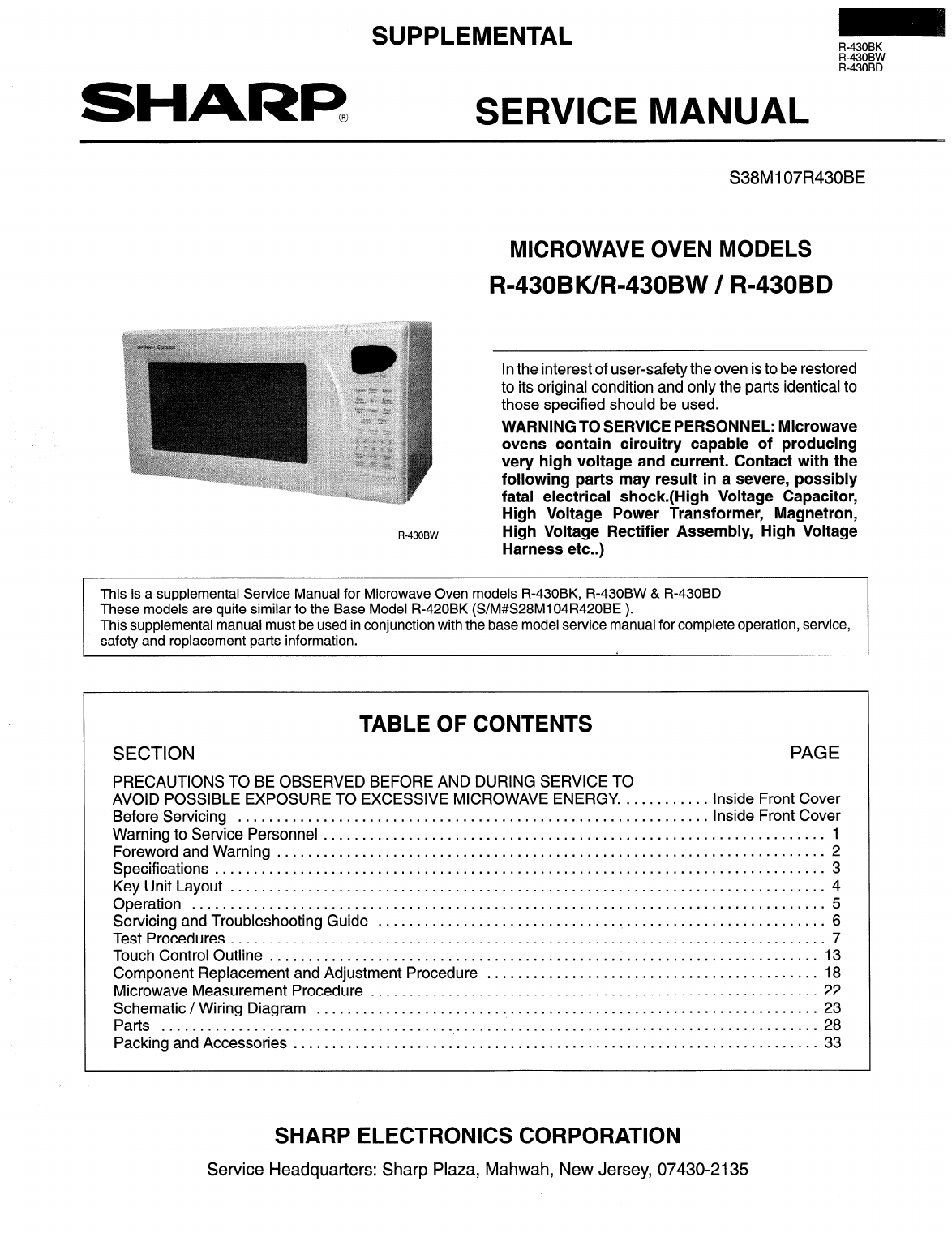
SUPPLEMENTAL SHARF? SERVICE MANUAL R-430BK R-430BW R-430BD S38Mi 07R430BE MICROWAVE OVEN MODELS R-430BK/R-430BW / R-430BD In the interest of us
R-430BK R-430BW R-430BD TEST PROCEDURES Procedure Letter Component Test G . Touch Control Panel Assembly Test (Confinued) When testing is c
R-430BK EEY TEST PROCEDURES .’ Procedure Letter Component Test 1. Continued Procedures to be taken when the foil pattern of the printed wiring
R-430BK R-430BW R-430BD TEST PROCEDURES Procedure Letter Component Test J Compu Defrost Test 1. Place one cup of water in the center of t
R-430BK EEY Procedure Letter Component Test L . AH Sensor Test Checking the initial sensor cooking condition 1. The oven should be plug
R-430BK R-430BW R-430BD Procedure Letter Component Test L. Checking the Control Unit (Confinued) 6. Disconnect the wire leads to the prima
R-430BK E%dl OUTLINE OF TOUCH CONTROL PANEL The touch control section consists of the following units as shown in the touch control pan
R-430BK R-430BW R-430BD The I/O signals of the LSI (IZA866DR) is detailed in the following table. ( Pin No. 1 Signal 1 I/O 1 Description
R-430BK R-430BW R-430BD Signal I/O Description Pin No. 22 P30 OUT Signal to sound Buzzer (2.0 kHz). 0.1 sec. B: completion sound 23 P31 O
R-430BK R-430BW R-430BD Pin No. Signal I/O Description 80-84 PIO-PI4 OUT Used for Initial balancing of the bridge circuit (absolute humidi
, . .- Precautions for Handling Electronic Components This unit uses CMOS LSI in the integral part of the cir- cuits. When handling th
R-430BK R-430BW R-430BD ( 1 a (b) ( ) C (d) ( ) e Do not operate or allow the oven to be operated with the door open. Make the followin
R-430BK R-430BW R-430BD COMPONENT REPLACEMENT/ADJUSTMENT PROCEDURE icrowave ovens contain circuitry capable of producing very high voltage
R-430BK E%F ABSOLUTE HUMIDITY SENSOR CIRCUIT Structure of Absolute Humidity Sensor the sensor cooking of the unit. The absolute humidity
R-430BK R-430BW R-430BD AH SENSOR DUCT REMOVAL 1. 2. 3 . 4. 5. 6. Disconnect the power supply cord. Open the oven door and block it open.
R-430BK R-430BW R-430BD AH SENSOR ORIENTATION 8t HARNESS ROUTING AH Sensor Orientation Mounting Screw AH densor AH Sensor Duct Figure l-1 6 O
R-430BK R-430BW R-430BD MICROWAVE MEASUREMENT PROCEDURE After adjustment of the door, interlock and monitor switches are completed individu
I 0 n In u 0 m D I n?_l- ha n__- -If*! - __ uoor uosea, LOOK u-r Lonamon MONITOR FUSE I BLK I 1 RED MAGNETRON TEMP. RED CAVITY TEMP. FUSE I--
R-430BK R-430BW R-430BD - - - - - -0 I CE I ’ 92 A , 00’ I I I I I I I I I I I I I I I I I I I I I I I I I I I I 24
1 2 3 4 5 6 AC1 2OV 60Hz TURNTABLE MOTOR OVEN LAMP FAN MOTOR MICRO I , ~ w R4 27 ICI01 Q2 2SB1238 Dl-D4 4 :I b/ 1 - 1 T' 4 lIESI D5 D6 R5 4.7k
R-430BK R-430BW R-430BD A B C D E F G ~ H 1 2 3 4 5 6 Printed Wiring Board of Power Unit 1 2 3 4 5 6 27
SERVICE MANUAL SHARI? Microwave Ovens R=430BK/R=430BW/R=43OBD Foreword This manual has been prepared to provide Sharp Electronics Corporatio
R-430BK R-430BW R-430BD Contact your nearest SHARP Parts Distributor to order. For location of SHARP Parts Distributor, Please call Toll-
R-430BK R-430BW R-430BD Ref No. Part No. Q Description Qty Code Control Panel 3-l / CPWBFBOllMRUO- M Control unit' 1 BK 3-1A QCNCMA4
R-430BK R-430BW R-430BD A A Ref No. Part No. Q Description Qty Code Door 4- 0 CDORFB217MRKO M Door assembly(R-43OBK) 1 BE 4- 0 CDORFB2
r R-430BK R-430BW R-430BD 4 I A z -I 3 1 I I I 1 4 5 I I I 6 Cavity Assembly 3 Q / Q 5-3 : 0 2-a 9 1-12
R-430BK R-430BW R-430BD 1 2 3 4 5 6 4 - 3 - - J - 1 - E - F - G - H Control Panel Assembly Q 4-o Door Assembly r---- --- ---------~-___- -----
. . ., . .: _:^ Wire Harnesses * Actual harnesses may be different than illustrations. 4 * TRAY HOLDER a OPERATlON MANUAL d> * PACKING
R-430BK R-430BW R-430BD SHARR ‘980 SHARP CORP. (3M2.70E) Printed in U.S.A.
R-430BK R-430BW R-430BD WARNING TO SERVICE PERSONNEL Microwave ovens contain circuitry capable of producing very high voltage and current
R-430BK R-430BW R-430BD SPECIFICATIONS Item Power Requirements Description 120 Volts 14 Amperes 1650 Watts 60 Hertz Single phase, 3 wire grounde
R-430BK R-430BW R-430BD Key Unit Layout a. Indicators. b. Lighted digital display. c. Custom Help. Features user friendly communications d
The following is a description during oven ope ration. OPERATION DESCRIPTION OF OPERATING SEQUENCE of compon Sensor Cooking Condition ent
R-430BK R-430BW R-430BD When troubleshooting the microwave oven, it is helpful to follow the sequence of operation in performing the check
R-430BK R-430BW R-430BD Procedure Letter Component Test G . Touch Control Panel Assembly Test The touch control panel consists of circuits
Related products and manuals for Microwaves Sharp R-430EK
 (44 pages)
(16 pages)
(28 pages)
(44 pages)
(16 pages)
(28 pages)
 (28 pages)
 (272 pages)
(70 pages)
(20 pages)
(20 pages)
(32 pages)
(1 pages)
(62 pages)
(44 pages)
(1 pages)
(20 pages)
(2 pages)
(2 pages)
(272 pages)
(70 pages)
(20 pages)
(20 pages)
(32 pages)
(1 pages)
(62 pages)
(44 pages)
(1 pages)
(20 pages)
(2 pages)
(2 pages)
 (28 pages)
© 2020, manymanuals.com. All rights reserved. | 0.052 s |
 Manymanuals.com
 Manymanuals.de
 Manymanuals.fr
 Manymanuals.it
 Manymanuals.pl
 Manymanuals.cz
 Manymanuals.es
 Manymanuals-pt.com
Comments to this Manuals