Sharp R-408HWM Service Manual
Browse online or download Service Manual for Microwaves Sharp R-408HWM. Sharp R-408HWM Service manual User Manual
- Page / 44
- Table of contents
- BOOKMARKS
- SERVICE MANUAL 1
- (RD21101U) 2
- (RD81001 U) 2
- Don’t Touch ! 4
- Danger High Vol 4
- Before Servicing 4
- After repairing 4
- SPECIFICATIONS 5
- Grounding Instructions 6
- Diagram 6
- I 5 I 6 7
- OPERATION 8
- Monitor 9
- / Switch 9
- SERVICING 10
- Troubleshooting Guide 11
- Problem 11
- Cook Condition 11
- Possible Cause 11
- Test Procedure 11
- TEST PROCEDURES 12
- Component Test 16
- Procedure Letter 16
- G-11 19
- Key Unit 20
- Control Unit 20
- DESCRIPTION OF LSI 21
- I 3o I XIN I IN I 22
- VCCNREF 23
- Approx. 1 Ma 24
- Outer Case Removal 26
- Power Transformer Removal 26
- Capacitor Removal 26
- Magnetron Removal 26
- Magnetron Installation 27
- Turntable Motor 27
- Removal 27
- Turntable Motor Re-install 28
- Cooling Fan Motor Removal 28
- DOOR DISASSEMBLY 30
- Interlock Switch Test 31
- Microwave Leakage Test 31
- Schematic Diagram 32
- 1 2 3 34
- 1 I 2 I 34
- BROWNER 36
- RY3 RY2 MICRO 36
- PARTS LIST 37
- 1 2 3 4 5 6 40
- Wire Harnesses 41
- Packing and Accessories 41
Summary of Contents
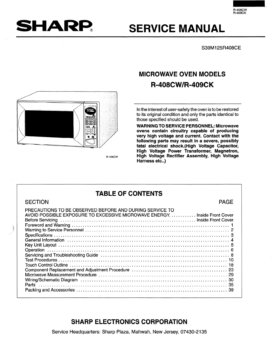
R-408CW R-409CK SHARP@ SERVICE MANUAL R-408CW S39M125R408CE MICROWAVE OVEN MODELS R-408CW/R=409CK In the interest of user-safety the oven is t
SERVICING When troubleshooting the microwave oven, it is helpful to follow the sequence of operation in performing the checks. Many of t
Troubleshooting Guide Problem mamp does not light at all. Oven lamp lights, but fan motor and turntable motor do not operate. Oven does not
TEST PROCEDURES Procedure Letter Component Test A . Magnetron Assembly Test 1. Disconnect the power supply cord, and then remove outercase
TEST PROCEDURES Procedure Letter Component Test C . High Voltage Rectifier Test 1. Disconnect the power supply cord, and then remove oute
TEST PROCEDURES Procedure Letter Component Test E . Continued Primary Interlock Relay (RY-2) 1. Disconnect the power supply cord, and then
IEE? TEST PROCEDURES Procedure Letter Component Test E. Continued Open Monitor Fuse I. Disconnect the power supply cord, and then remove
Procedure Letter Component Test G . Continued Touch Control Panel Assembly Test 1. Key Unit 1. Disconnect the power supply cord, and then
TEST PROCEDURES Procedure Letter Component Test H . Relay Test 1. Disconnect the power supply cord, and then remove outer case cabinet. 2
TEST PROCEDURES Procedure Letter Component Test I . Continued Procedures to be taken when the foil pattern of the printed wiring board (PWB) is ope
Procedure Letter Component Test J Compu Defrost Test WARNING : The Oven should be fully assembled before following procedure. 1. Place on
( ) a (b) () C (d) () e Do not operate or allow the oven to be operated with the door open. Make the following safety checks on all ovens t
OUTLINE OF TOUCH CONTROL PANEL The touch control section consists of the following units as shown in the touch control panel circuit:
DESCRIPTION OF LSI LSI The I/O signals of the LSI (IZA495DR) is detailed in the following table. Pin No. Signal I/O Description 1-2 VL2
1 Pin No. 1 Signal 1 I/O 1 Description 1 22 1 P44 / IN 1 Signal similar to P45. When either G-l 1 line on key matrix is touched, a co
Pin No. Signal I/O Description 51-72 SEG21-SEGO OUT Segment data signal. Connected to LCD. The relation between signals are as follows: LSI
Precautions for Handling Electronic Components This unit uses CMOS LSI in the integral part of the cir- cuits. When handling these part
Microwave ovens contain circuitry capable of producing very high voltage and current, contact with the following parts may result in se
Please refer to “OVEN PARTS, CABINET PARTS, CONTROL PANEL PARTS, DOOR PARTS” When carrying out any of the following removal procedures:
1. 2. 3. 4. 5. 1. 2. 3. 4. 5. 6. 7. 8. COMPONENT REPLACEMENT / ADJUSTMENT PROCEDURE Magnetron Installation Install magnetron assembly to the wa
COMPONENT REPLACEMENT / ADJUSTMENT PROCEDURE 1. 2. 1. 2. 3. 4. 5. 6. Turntable Motor Re-install Remove any sharp edges on the turntable mot
COMPONENT REPLACEMENT/ADJUSTMENT PROCEDURE Door Sensing Switch /Secondary Interlock Switch and Monitor Switch Adjustments 1. 2. 3. 1. 2. Disconne
SERVICE MANUAL SHARR Microwave Ovens R=408CW/R=409CK Foreword This manual has been prepared to provide Sharp Electronics Corporation person
E%%E! _ DOOR DISASSEMBLY Removal 1. Disconnect the power supply cord. 2. Push the open button and open the door slightly. 3. Insert a
Fb408CW R-409CK After adjustment of the door, interlock and monitor switches are completed individually or collectively, a IN- TERLOCK S
I t) l-l m 0 0 co D Door Closed, Cook Off Condition MAGNETRON TEMP. MONITOR FUSE I+= RED I A2 t---I FUSE RED Note RED 5 RY-2 RY-1 PRIMARY IN
1 r A B C D E F G A H I L 3 4 3 b I C I 1 2 3 4 5 31
1 2 3 4 5 6 4 CN-A AC OVEN LAMP TURNTABLE MOTOR FAN MOTOR AC MICRO DOOR SENSING I I SWITCH SH-6 \ \[Clj Power Unit Circuit CN-C 9PIN LEAD W
1 2 3 4 5 6 4 - B - c - D - E - F - G - H -E 4zmo’o 63 A9l/rlLtr 23 +-I N i 1 I I J - I 5 4 0 1 2 3 4 5 6 A - I3 - C - D - E - F - c - I- 33
1 2 3 4 5 6 \ - 5 - : - 1 - E - F - 3 - f- DIP SPl VH BROWNER RY3 RY2 MICRO Printed Wiring Board of Power Unit 1 2 3 4 5 6 34
PARTS LIST Contact your nearest SHARP Parts Distributor to order. For location of SHARP Parts Distributor, Please call Toll-Free; 1-800-BE-S
A A Ref No. Part No. Q Description Qty Code RYl-2 RRLY-A114DREO SPl RALM-AO14DREO Tl RTRNPBO13MREO Tl RTRNPAllODREO VRSl RH-VZBOOlMREO VRSl 3-2 3
R-408CW R-409CK 1 I I I A I w - 1 2 3 4 5 6 37
WARNING TO SERVICE PERSONNEL Microwave ovens contain circuitry capable of producing very high voltage and current. Con- tact with follo
1 2 3 4 5 6 Control Panel Assembly 4 A 3 B Door Assembly E E F F 1 I 2 I 3 I 4 I 5 I 6 38
1 2 3 4 5 6 Wire Harnesses * Actual harnesses may be different than illustrations. : Packing and Accessories TURNTABLE SUPPORT G * PACKING CA
SHARF? ‘990 SHARP CORP. (3M3.2E) Printed in U.S.A.
R-408CW R-409CK SPECIFICATIONS Item Description Power Requirements 120 Volts 13.3 Amperes 1550Watts 60 Hertz Single phase, 3 wire grounded Power
ommended that a separate circuit serving only this appliance be provided. When installing this appliance, observe all applicable codes
Key Unit Layout MINUTE PLUS INSTANT ACTION TO ADJUST QUANTITY -TOUCH PAD AGAIN 1 Ground Meat 2 Steaks/Chops 3 Chicken Pieces COMPU DEFROST 1 I
R-408CW R-409CK OPERATION Description of Operating Sequence The following is a description of component functions during oven operation: Of
DESCRIPTION AND FUNCTION OF COMPONENTS Cooling Fan Motor The cooling fan motor drives a blade which draws exter- nal cool air. This cool
Related products and manuals for Microwaves Sharp R-408HWM
 (12 pages)
(40 pages)
(20 pages)
(28 pages)
(16 pages)
(48 pages)
(28 pages)
(16 pages)
(10 pages)
(12 pages)
(40 pages)
(20 pages)
(28 pages)
(16 pages)
(48 pages)
(28 pages)
(16 pages)
(10 pages)
 (36 pages)
(33 pages)
(44 pages)
(20 pages)
(23 pages)
(4 pages)
(32 pages)
(31 pages)
(44 pages)
(18 pages)
(40 pages)
(36 pages)
(33 pages)
(44 pages)
(20 pages)
(23 pages)
(4 pages)
(32 pages)
(31 pages)
(44 pages)
(18 pages)
(40 pages)
© 2020, manymanuals.com. All rights reserved. | 0.036 s |
 Manymanuals.com
 Manymanuals.de
 Manymanuals.fr
 Manymanuals.it
 Manymanuals.pl
 Manymanuals.cz
 Manymanuals.es
 Manymanuals-pt.com
Comments to this Manuals